Tool box with pivoting seats for screwdriver tips

a tool box and screwdriver technology, applied in the field of tool boxes, can solve the problems of inconvenient user selection of screwdriver tips, and achieve the effect of reducing the disadvantage of the conventional tool box and / or obviating the disadvantag

Active Publication Date: 2008-02-19
YIH CHENG FACTORY
View PDF9 Cites 24 Cited by
  • Summary
  • Abstract
  • Description
  • Claims
  • Application Information

AI Technical Summary

Benefits of technology

[0005]The present invention is to mitigate and / or obviate the disadvantage of the conventional tool box.
[0006]The primary objective of the present invention is to provide a tool box having an efficiently clamping effect.
[0007]Another objective of the present invention is to provide a tool box, wherein each of the screwdriver tips is locked on the respective receiving member efficiently by the clamping effect of the elastic press piece of each of the receiving members, thereby preventing each of the screwdriver tips from being detached from the tool box when not in use.
[0009]A further objective of the present invention is to provide a tool box, wherein each of the receiving members is positioned in the main body temporarily when not in use, thereby preventing each of the receiving members from being pivoted relative to the main body freely.

Problems solved by technology

However, all of the screwdriver tips are mounted in the mounting recesses, so that a user has to in turn select the required screwdriver tip from the respective mounting recess, thereby causing inconvenience to the user in selection of the screwdriver tips.

Method used


Image

  • Tool box with pivoting seats for screwdriver tips
  • Tool box with pivoting seats for screwdriver tips
  • Tool box with pivoting seats for screwdriver tips

Examples


Embodiment Construction

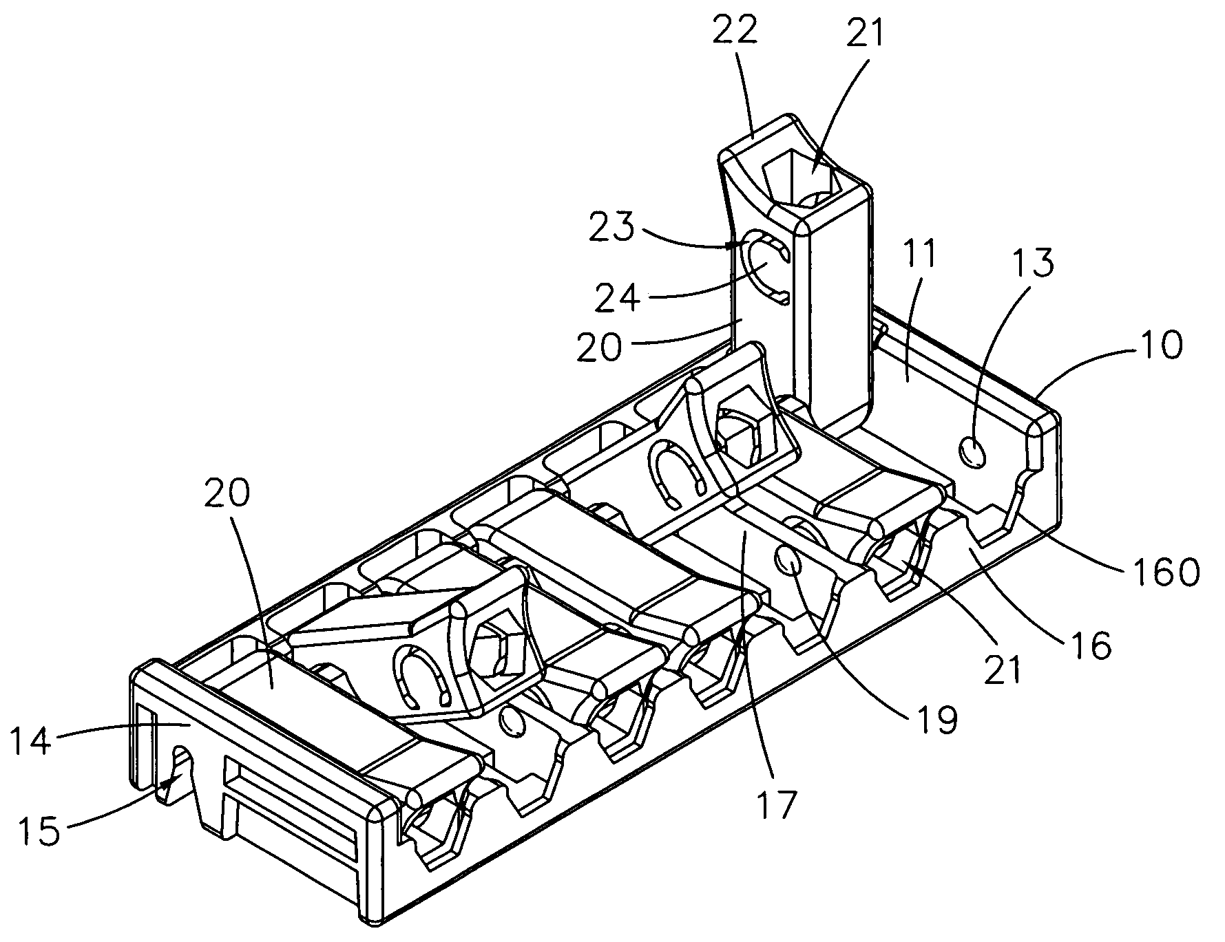
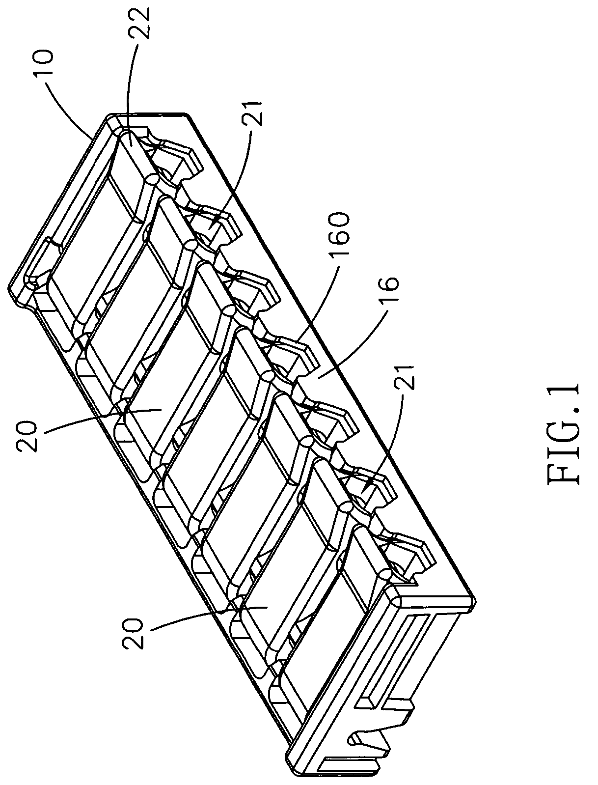
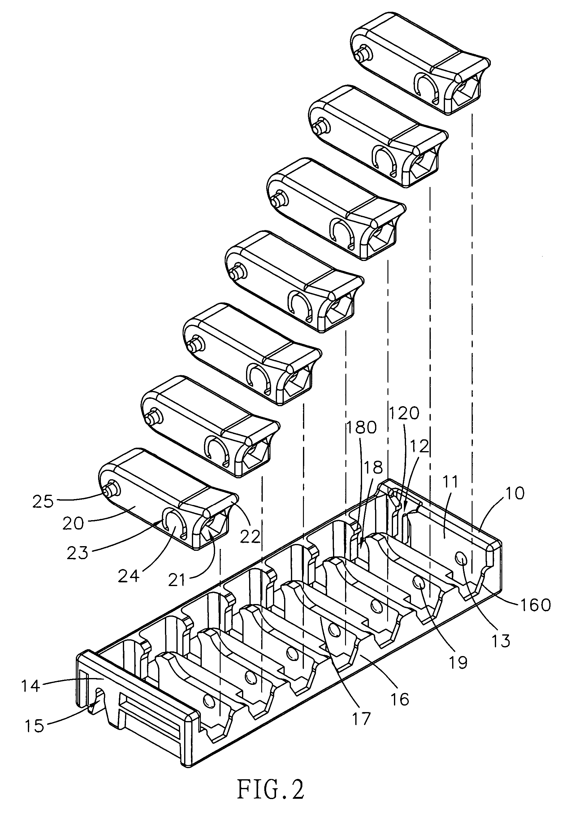
[0020]Referring to the drawings and initially to FIGS. 1-5, a tool box in accordance with the preferred embodiment of the present invention comprises a main body 10, and a plurality of juxtaposed receiving members 20 each pivotally mounted in the main body 10 for receiving a plurality of screwdriver tips 30.

[0021]The main body 10 has a first end wall 11, a second end wall 14 and an open side wall 16. The first end wall 11 of the main body 10 has a first end formed with a substantially U-shaped clamping slot 12 and a second end formed with a convex boss 13. The clamping slot 12 of the first end wall 11 of the main body 10 has an upper portion formed with two inwardly extended lips 120. The second end wall 14 of the main body 10 has an end formed with a shaft hole 15. The open side wall 16 of the main body 10 is formed with a plurality of openings 160 to allow passage of each of the screwdriver tips 30 as shown in FIG. 5.

[0022]The main body 10 has an inside formed with a plurality of ...


PUM


Abstract

A tool box includes a main body, and a plurality of juxtaposed receiving members each pivotally mounted in the main body for receiving a plurality of screwdriver tips. Thus, each of the screwdriver tips is locked on the respective receiving member efficiently by the clamping effect of the elastic press piece of each of the receiving members, thereby preventing each of the screwdriver tips from being detached from the tool box when not in use.

Description

BACKGROUND OF THE INVENTION[0001]1. Field of the Invention[0002]The present invention relates to a tool box, and more particularly to a tool box for storing screwdriver tips.[0003]2. Description of the Related Art[0004]A conventional tool box for storing screwdriver tips comprises a main body integrally formed with multiple mounting recesses for mounting the screwdriver tips. However, all of the screwdriver tips are mounted in the mounting recesses, so that a user has to in turn select the required screwdriver tip from the respective mounting recess, thereby causing inconvenience to the user in selection of the screwdriver tips.SUMMARY OF THE INVENTION[0005]The present invention is to mitigate and / or obviate the disadvantage of the conventional tool box.[0006]The primary objective of the present invention is to provide a tool box having an efficiently clamping effect.[0007]Another objective of the present invention is to provide a tool box, wherein each of the screwdriver tips is lo...

Claims


Application Information

Patent Timeline
Patent Type & Authority Patents(United States)
IPC IPC(8): B65D85/20A47F7/00B25H3/00B25H3/02
CPCB25H3/003
Inventor LIN, JACK
Owner YIH CHENG FACTORY
Why Eureka
Try Eureka