
Electrical plug-in connection

a plug-in connection and plug-in technology, applied in the direction of coupling device connection, coupling parts engagement/disengagement, electrical apparatus, etc., can solve the problems of union nut being detached, time required for screwing and unscrewing the union nut when producing or disconnecting the plug-in connection, etc., to achieve the effect of improving the plug-in connection

Inactive Publication Date: 2008-02-19
CONINVERS ELEKTROTECHN BAUELEMENTE
View PDF10 Cites 7 Cited by
  • Summary
  • Abstract
  • Description
  • Claims
  • Application Information

AI Technical Summary

Benefits of technology

"The invention is a plug-in connection that improves reliability and ease of use. It achieves this by preventing the union nut from detaching during vibration movements and making it faster to screw the connection. The union nut has internal threads that are segmented and have a different profile to prevent interference with external threads. The plug part and mating plug part have complementary external threads that can be easily engaged with the union nut. The front sides of the parts are moved twice as far towards each other in comparison with conventional connectors, saving time. The first thread turn of the segmented internal thread of the union nut ensures a secure connection and can be easily fitted. The invention also allows for easy locking of the parts together."

Problems solved by technology

One disadvantage of these known plug-in connections is the time required for screwing and unscrewing the union nut when producing or when disconnecting the plug-in connection.
Another disadvantage is the fact that, in the case of a sealing ring which is arranged between the front faces of the plug part and the mating plug part, the sealing ring is not always pinched such that it seals the annular gap between the plug part and the mating plug part reliably against the ingress of moisture.
This also results in the union nut becoming detached by means of vibration movements.

Method used


Image

  • Electrical plug-in connection
  • Electrical plug-in connection
  • Electrical plug-in connection

Examples


Embodiment Construction

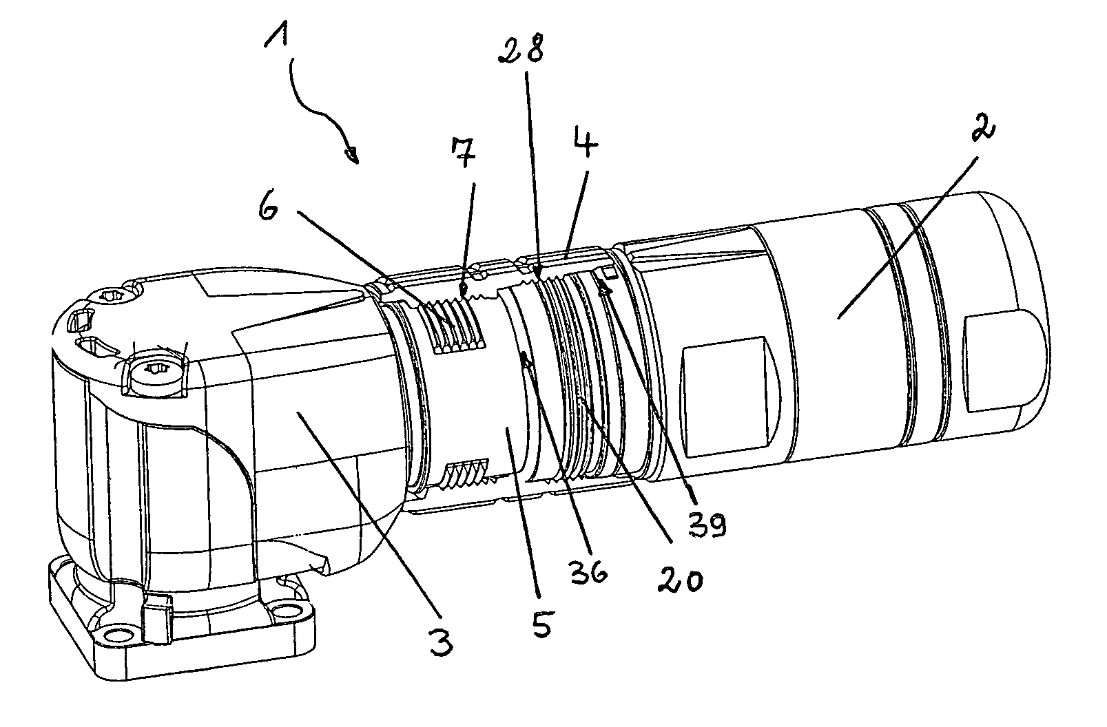
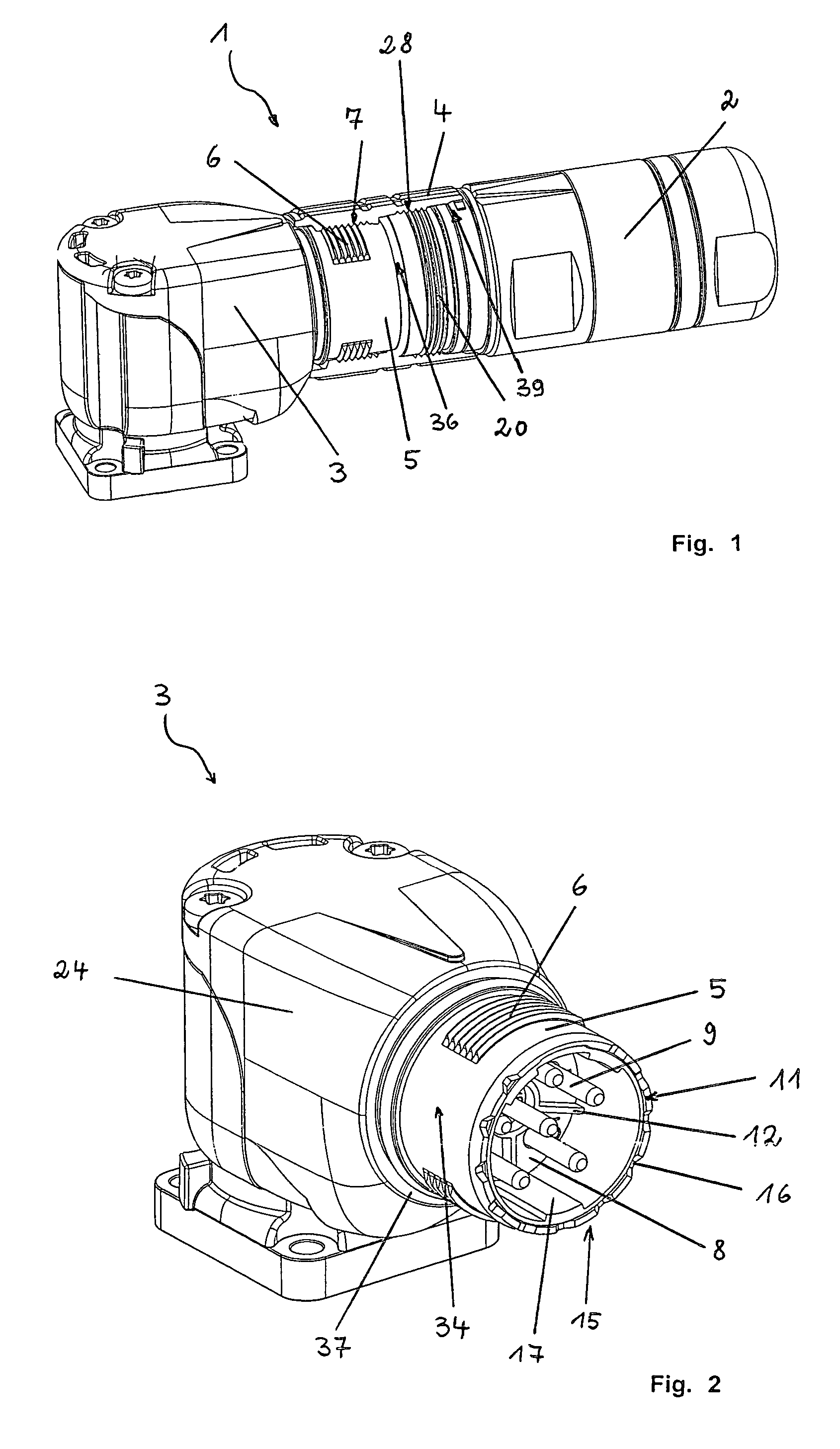
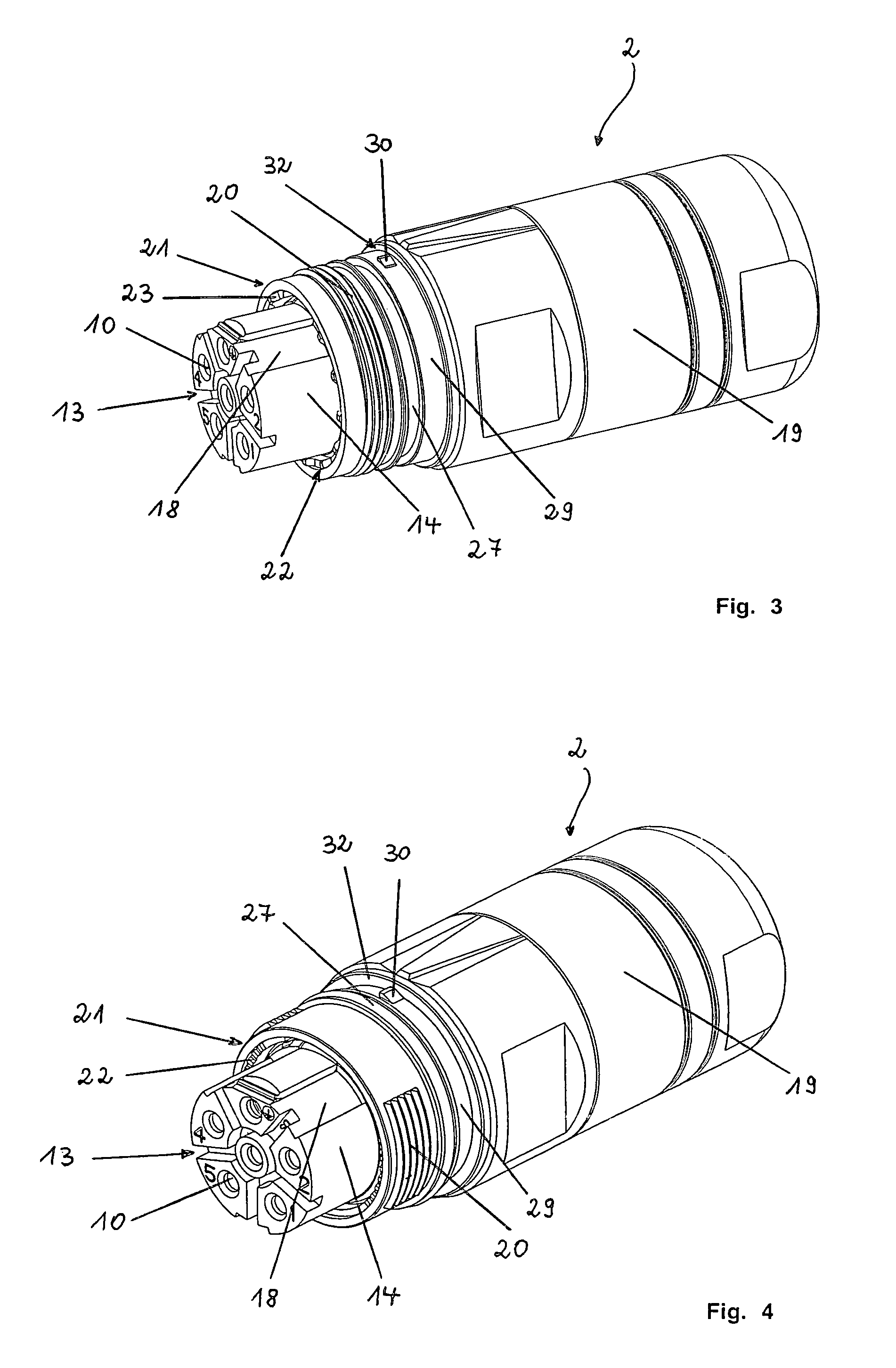
[0024]The plug-in connection 1 according to the invention and illustrated in FIG. 1 essentially comprises a plug part 2, a mating plug part 3 and a union nut 4. The plug part 2 is plugged together with the mating plug part 3 and is screwed to the mating plug part 3 by means of the union nut 4 borne by the plug part 2. The plug part 2 produces a large number of electrical connections to the mating plug part 3, which is fixed to a machine housing (not illustrated). The plug part 2 and the mating plug part 3 are shown individually, in the state in which they are not plugged together, in FIGS. 4 and 2.

[0025]The mating plug part 3 has a thread sleeve 5 having an external thread 6. The external thread 6 has a plurality of thread turns and is of a segmented design. It has three thread-free regions 34 in the plug-in direction, which are arranged such that they are distributed asymmetrically over the circumference of the thread sleeve 5. An internal thread 7, which is equivalently matched to...


PUM


Abstract

Electrical plug-in connection (1), having a plug part (2) and a mating plug part (3), which can be plugged together and produce a large number of electrical plug-in connections, at least the plug part (2) or the mating plug part (3) bearing, on its body (19, 24), a union nut (4), which can be screwed to the mating plug part (3) or the plug part (2) and secures the plug-in connection (1) against becoming disconnected in an undesirable manner. The union nut (4) has, at both of its ends, an internal thread (28, 7) for simultaneously screwing it to the plug part (2) and the mating plug part (3), the internal threads (7, 28) being formed in the opposite direction.

Description

BACKGROUND OF THE INVENTION[0001]The invention relates to an electrical plug-in connection, comprising a plug part and a mating plug part, which can be plugged together and produce a large number of electrical connections, at least the plug part or the mating plug part bearing, on its body, a union nut, which can be screwed to the mating plug part or the plug part and secures the plug-in connection against becoming disconnected in an undesirable manner, the union nut having, at its ends, an internal thread for screwing it to the plug part and the mating plug part, and the internal threads being formed in the opposite direction.[0002]Such plug-in connections are generally known and are in use and are preferably used in the construction of electrical appliances, machines, vehicles and systems. The intention is therefore to provide the fitter or the user with a possibility of producing or detaching an electrical connection simply, rapidly and safely. In this case, the connection techno...

Claims


Application Information

Patent Timeline
Patent Type & Authority Patents(United States)
IPC IPC(8): H01R13/62
CPCH01R13/622H01R13/5202H01R13/5219
Inventor SCHOLLER, JOHANNFREDL, SONJA
Owner CONINVERS ELEKTROTECHN BAUELEMENTE
Learn More