Method, apparatus, and computer program product for facilitating modeling of a combinatorial logic glitch at an asynchronous clock domain crossing

a technology of combinatorial logic and applied in the field of circuits, can solve the problems of inability to correctly identify problems caused by existing simulation approaches, difficulty in verifying logic at asynchronous clock domain crossing, and difficulty in modeling combinatorial logic glitches. the effect of modeling

Inactive Publication Date: 2008-02-19
GOOGLE LLC
View PDF3 Cites 27 Cited by
  • Summary
  • Abstract
  • Description
  • Claims
  • Application Information

AI Technical Summary

Benefits of technology

[0007]Further, the asynchronous clock domain crossing may comprise a transmitting sequential element and a receiving sequential element, with the combinatorial logic being disposed between the transmitting sequential element and the receiving sequential element. In this implementation, the method further includes inserting the simulation value of X into the combinatorial logic after the transmitting sequential element, and the converting includes providing an X-to-random conversion module inserted into the asynchronous clock domain crossing prior to the receiving sequential element, wherein the X-to-random conversion module automatically performs the converting. The inserting of the simulation value of X into the combinatorial logic can be facilitated by inserting an X generating Wire Asynchronous Model into the asynchronous clock domain crossing between the transmitting sequential element and the combinatorial logic to facilitate automatic propagation of the simulation value X through the combinatorial logic during metastability periods of the combinatorial logic.

Problems solved by technology

Logic at asynchronous clock domain crossings is conventionally difficult to verify.
Without metastability, a clock domain crossing problem may exist if a signal change randomly arrives either before or after the metastable period, or may occur due to races between parallel paths of the logic, which are known as clock domain crossing glitches.
However, existing simulation approaches often do not correctly identify problems caused by clock domain crossing glitches.

Method used


Image

  • Method, apparatus, and computer program product for facilitating modeling of a combinatorial logic glitch at an asynchronous clock domain crossing
  • Method, apparatus, and computer program product for facilitating modeling of a combinatorial logic glitch at an asynchronous clock domain crossing
  • Method, apparatus, and computer program product for facilitating modeling of a combinatorial logic glitch at an asynchronous clock domain crossing

Examples


Embodiment Construction

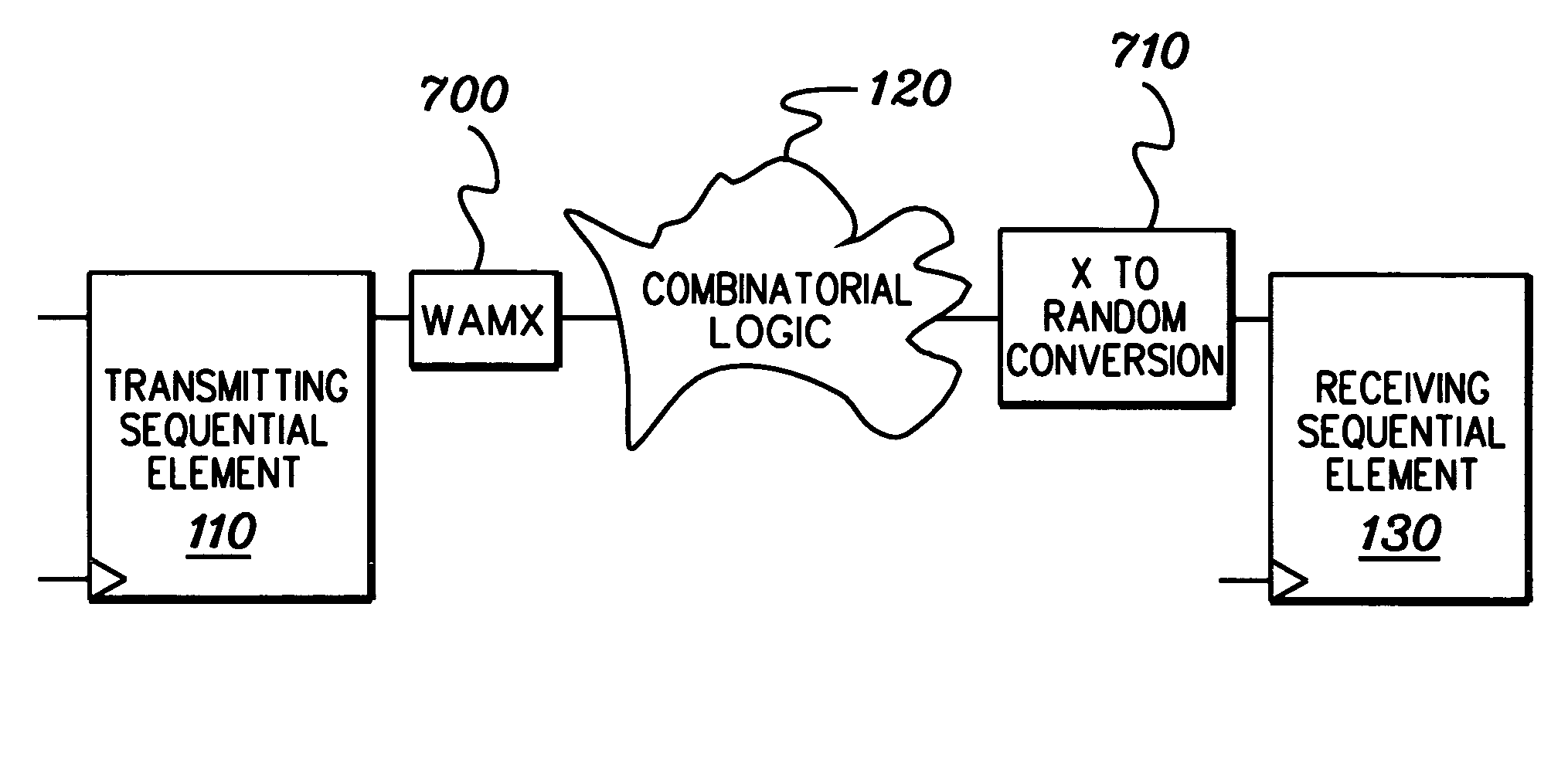
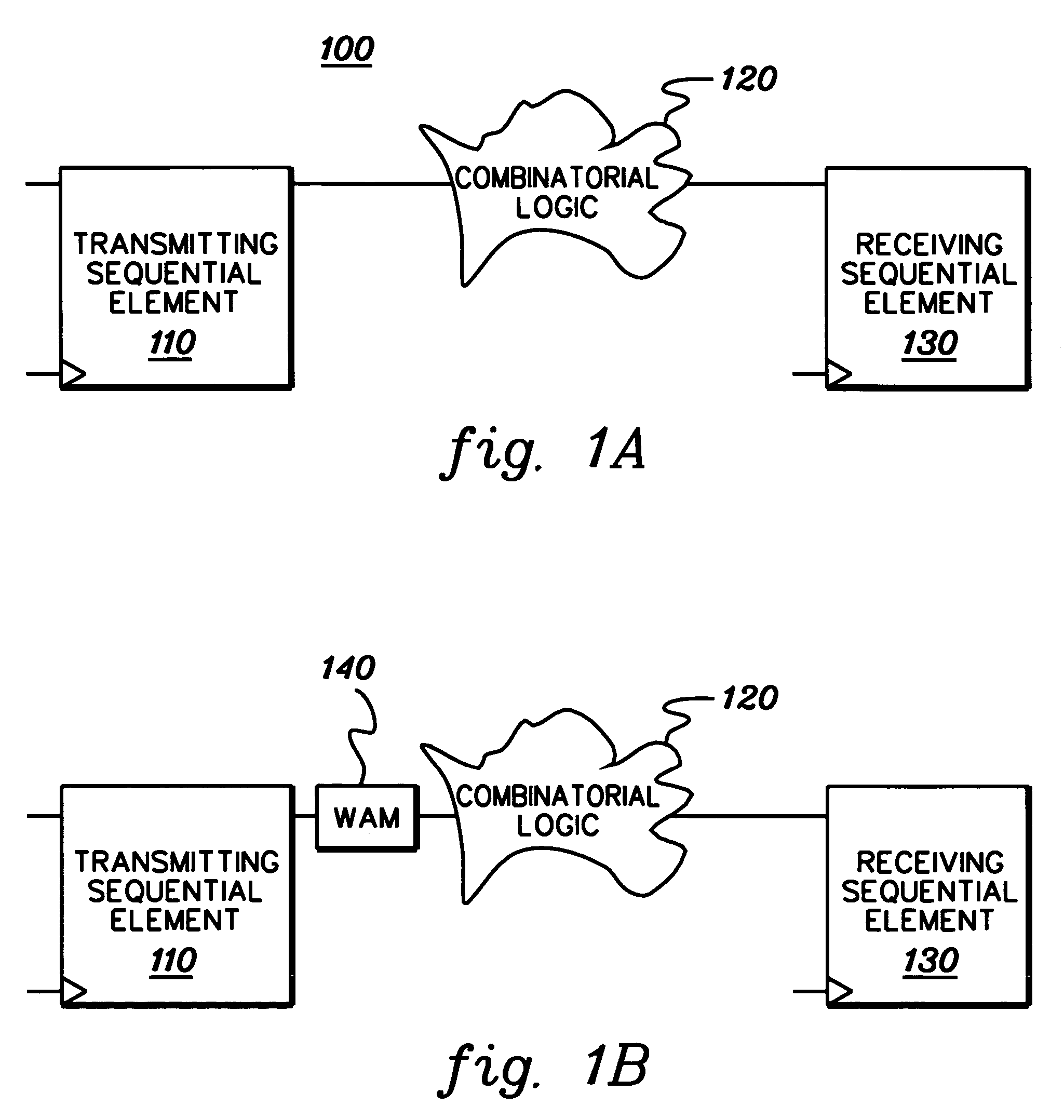
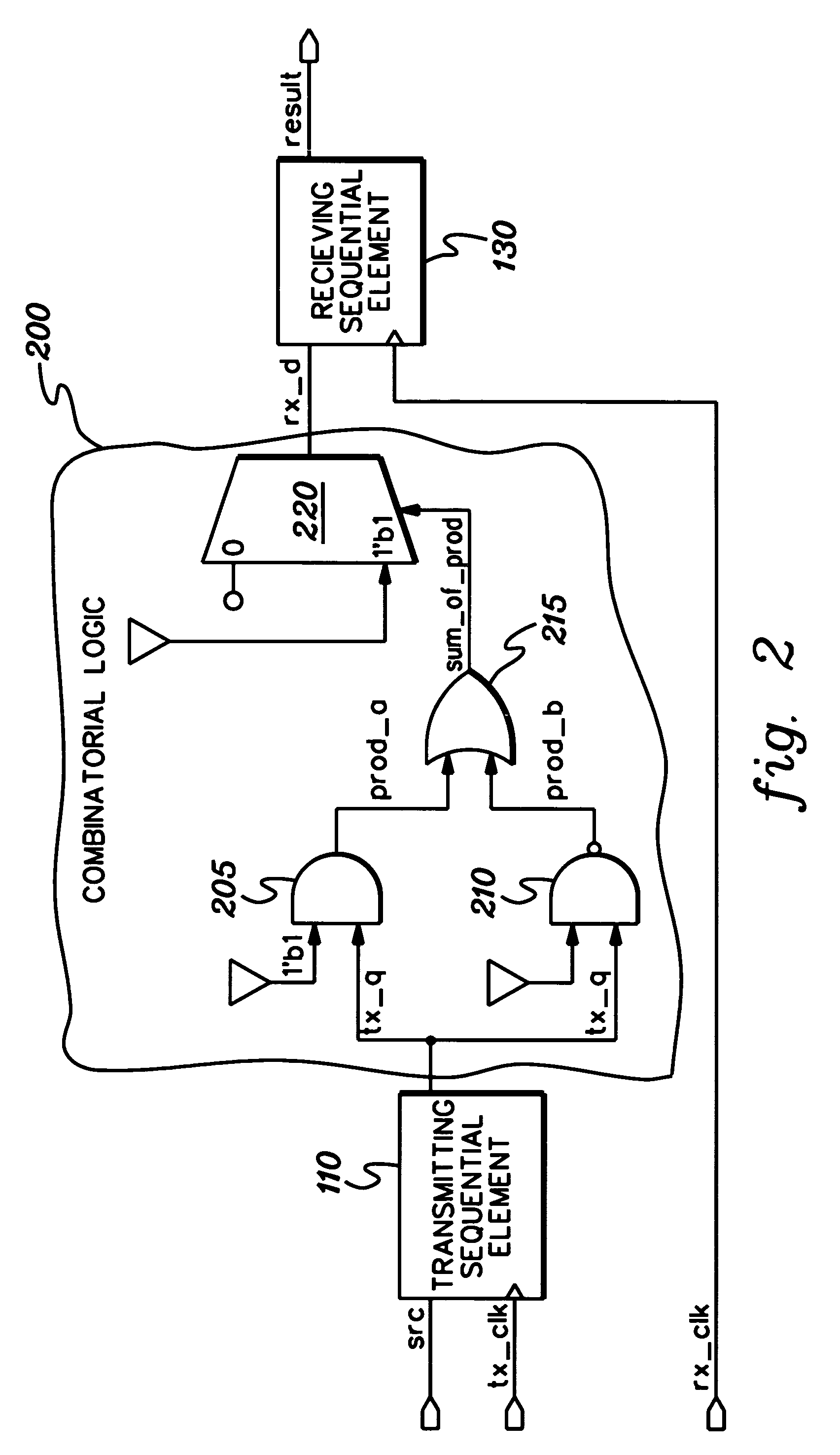
[0020]Presented herein is a technique for simulation modeling of circuitry. More particularly, disclosed herein is a technique for modeling combinatorial logic at an asynchronous clock domain crossing. A clock domain crossing glitch is often missed when a signal from a transmitting sequential element fans out and then converges in a combinatorial logic cloud between the clock domains. By way of example, FIG. 2 depicts a combinatorial logic cloud 200 wherein a signal tx_q fans out into AND logic 205 and NAND logic 210 and later converges in the sum_of_prod output from OR logic 215 between the tx_clk and rx_clk domains. In this example, the tx_clk signal clocks the transmitting sequential element 110, while the rx_clk signal clocks the receiving sequential element 130 at the clock domain crossing. The sum_of_prod signal controls a multiplexer 220, the output rx_d of which is the data value to the receiving sequential element 130. The logic value of 1, which is shown in FIG. 2 as 1′b1 ...


PUM


Abstract

A method, apparatus and computer program product are provided for facilitating combinatorial logic modeling at an asynchronous clock domain crossing. The modeling technique employs a simulation value of X in combinatorial logic at the asynchronous clock domain crossing of a circuit being modeled to facilitate modeling of a potential combinatorial logic glitch at the crossing during metastability periods thereof. Employing the simulation value of X includes: generating one or more equivalent functional equations for one or more combinatorial paths through the combinatorial logic at the crossing; propagating the simulation value of X through the combinatorial logic using the at least one equivalent functional equation; and then converting the simulation value of X at an output of the combinatorial logic of the asynchronous clock domain crossing to a random logic value for further propagation within the circuit being modeled.

Description

TECHNICAL FIELD OF THE INVENTION[0001]This invention relates generally to modeling circuits, and more particularly, to a technique for modeling glitch-prone combinatorial logic at an asynchronous clock domain crossing of an ASIC design.BACKGROUND OF THE INVENTION[0002]Integrated circuits often have multiple clock domains. In each clock domain, a domain clock is driven by a clock operating at a particular frequency that is different from the clock frequency of the clocks in other clock domains. An asynchronous clock domain crossing refers to an interface between two of these differently clocked logic domains. Often, logic such as combinatorial logic exists at an asynchronous clock domain crossing in ASIC designs. Logic at asynchronous clock domain crossings is conventionally difficult to verify. This is because the receiving sequential element at the crossing may or may not capture a correct or consistent data value when a transmitting sequential element at the crossing (from the asy...

Claims


Application Information

Patent Timeline
Patent Type & Authority Patents(United States)
IPC IPC(8): G06F17/50
CPCG06F17/5022G06F30/33
Inventor SCHUPPE, RAYMOND W. M.
Owner GOOGLE LLC
Why Eureka
Try Eureka