Methods and apparatus for machining components

a gas turbine engine and component technology, applied in the field of gas turbine engines, can solve the problems of laborious process, unfavorable leakage flow between the upstream and downstream portions of the rotor, and the method for cutting a seal wire groove is relatively complex

Inactive Publication Date: 2008-02-26
GENERAL ELECTRIC CO
View PDF22 Cites 25 Cited by
  • Summary
  • Abstract
  • Description
  • Claims
  • Application Information

AI Technical Summary

Problems solved by technology

Specifically, when the component is a gas turbine engine blade, accurate manufacturing of the blade may be one of the most significant factors affecting an overall cost of fabrication of the gas turbine engine, as well as subsequent modifications, repairs, and inspections of the blade.
During operation, a pressure differential is created between the compressor blade pressure side and the compressor blade suction side which may result in an undesirable leakage flow between the upstream and downstream portions of the rotor.
Removing the machining assembly from the milling machine and re-installing separate components for each set of compressor blades is a relatively labor intensive process since each holding fixture must be installed on the milling machine prior to cutting the seal wire groove in the next set of blades.
Since the method for cutting a seal wire groove is relatively complex, at least one known manufacturer machines a plurality of seal grooves without changing the holding fixture to faciliate reducing costs of fabrication.

Method used


Image

  • Methods and apparatus for machining components
  • Methods and apparatus for machining components
  • Methods and apparatus for machining components

Examples


Embodiment Construction

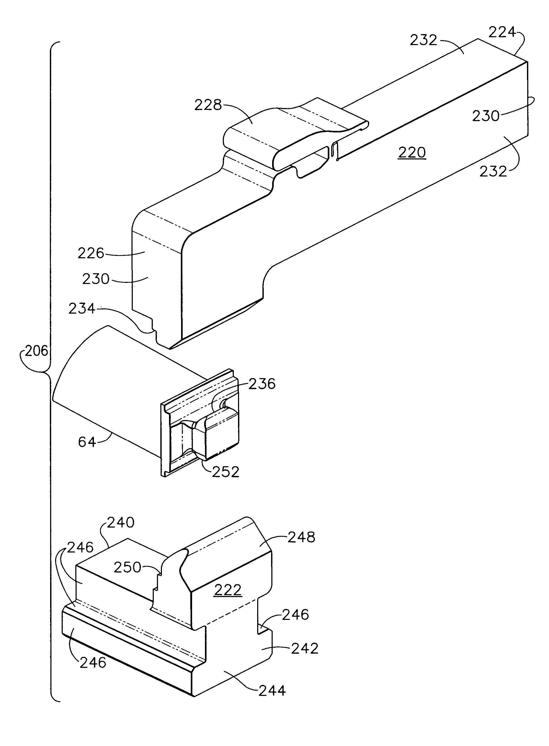
[0016]As used herein, the terms “manufacture” and “manufacturing” may include any manufacturing process. For example, manufacturing processes may include grinding, finishing, polishing, cutting, machining, inspecting, and / or casting. The above examples are intended as exemplary only, and thus are not intended to limit in any way the definition and / or meaning of the terms “manufacture” and “manufacturing”. In addition, as used herein the term “component” may include any object to which a manufacturing process is applied. Furthermore, although the invention is described herein in association with a gas turbine engine, and more specifically for use with a compressor blade for a gas turbine engine, it should be understood that the present invention may be applicable to any component and / or any manufacturing process. Accordingly, practice of the present invention is not limited to the manufacture of compressor blades or other components of gas turbine engines.

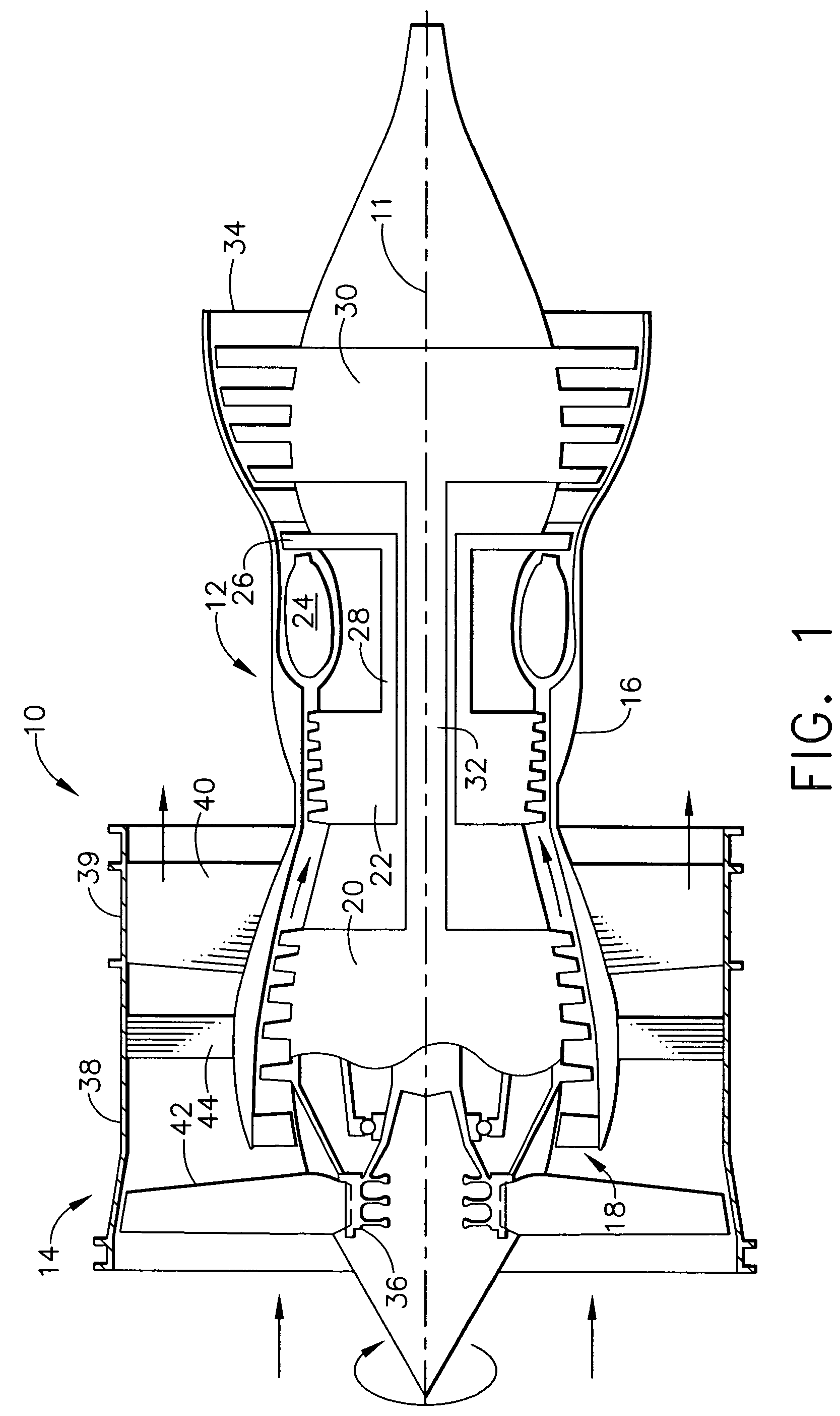
[0017]FIG. 1 is a schematic ...


PUM

PropertyMeasurementUnit
timeaaaaaaaaaa
fabricating timeaaaaaaaaaa
pressureaaaaaaaaaa

Abstract

A method of using a machining assembly to machine a plurality of different turbine components that include a dovetail having a contoured profile. The method includes removably coupling a first set of retainers into the machining assembly, the first set of retainers include an upper portion having a profile that substantially mirrors a portion of the first dovetail, and a lower portion having a profile that substantially mirrors an opposite side of the first dovetail, coupling a first turbine component between the upper and lower portions such that the first turbine component is secured by the first set of retainers, coupling the machining assembly into a milling machine, and machining at least one seal groove into the dovetail of the first turbine component.

Description

BACKGROUND OF THE INVENTION[0001]This invention relates generally to gas turbine engines, and more specifically to methods and apparatus for machining gas turbine engine components.[0002]Accurate manufacturing of a component may be a significant factor in determining a fabricating time of the component. Specifically, when the component is a gas turbine engine blade, accurate manufacturing of the blade may be one of the most significant factors affecting an overall cost of fabrication of the gas turbine engine, as well as subsequent modifications, repairs, and inspections of the blade. For example, at least some known gas turbine engines include a compressor for compressing air which is mixed with a fuel and channeled to a combustor wherein the mixture is ignited within a combustion chamber for generating hot combustion gases. At least some known compressors include a rotor assembly that includes at least one row of circumferentially spaced rotor blades. Each rotor blade includes an ...

Claims


Application Information

Patent Timeline
Patent Type & Authority Patents(United States)
IPC IPC(8): B23P15/04B23Q3/06F01D5/30B25B5/14F01D11/00F02C7/00
CPCB23Q3/063B24B41/06B25B5/14F01D25/285B24B19/14Y10T29/4932F05D2230/14F05D2240/55F05D2250/193Y10S269/909Y10T29/51Y10T29/49998Y10T29/49336Y10T29/49325Y10T409/303808
Inventor BOUCHARD, ERICUMNEY, MICHAEL ANTHONYAHTI, ROBERT ALLAN
Owner GENERAL ELECTRIC CO
Why Eureka
Try Eureka