

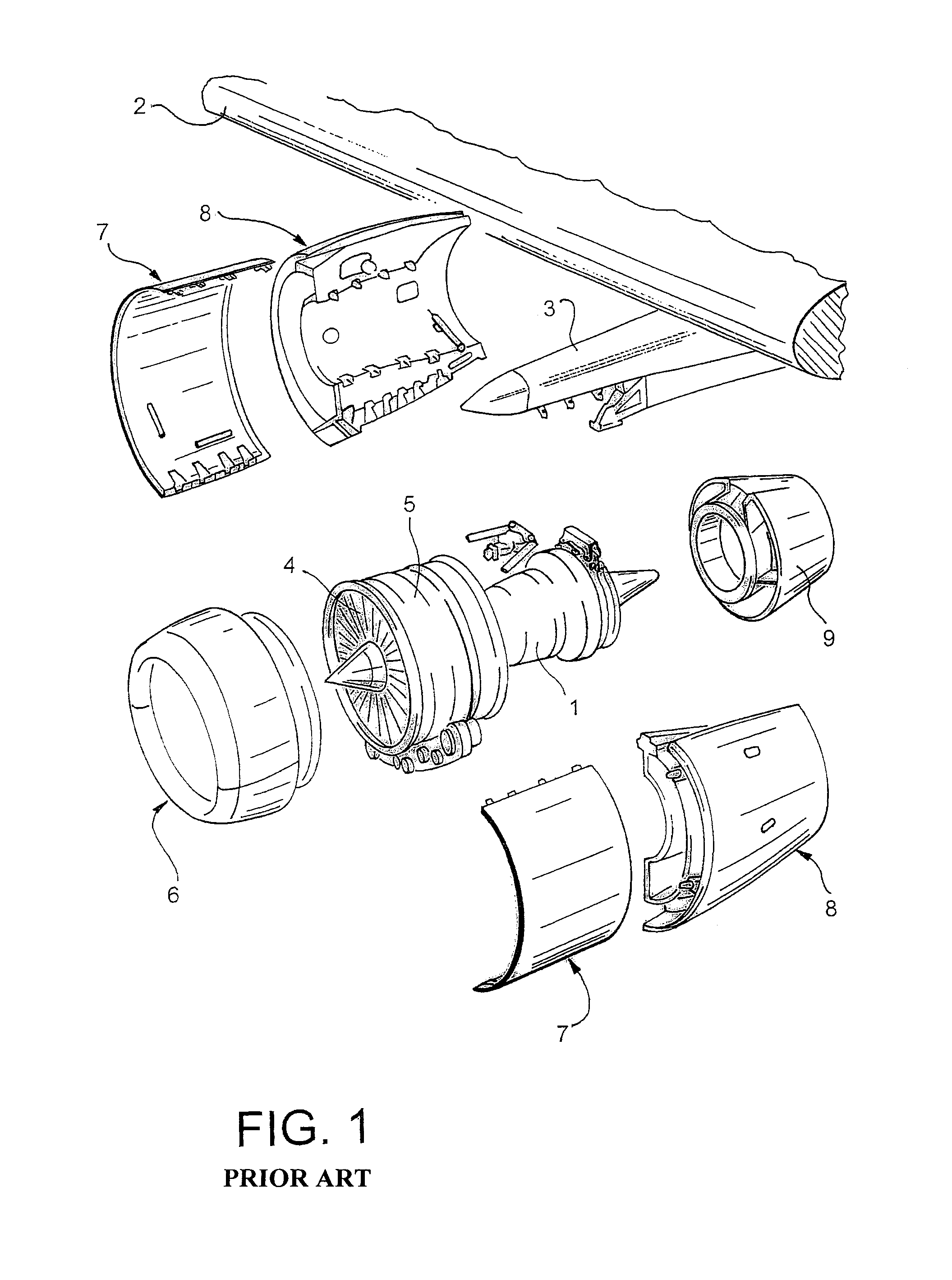
Aircraft engine in which there is a small clearance separating the fan cowls and the thrust inverter cowls
a technology of aircraft engine and fan cowl, which is applied in the field of aircraft engines, can solve the problems of increasing parasite drag, accelerating part wear, and increasing fuel consumption throughout the fligh
- Summary
- Abstract
- Description
- Claims
- Application Information
AI Technical Summary
Benefits of technology
Problems solved by technology
Method used
Image

Examples
first embodiment
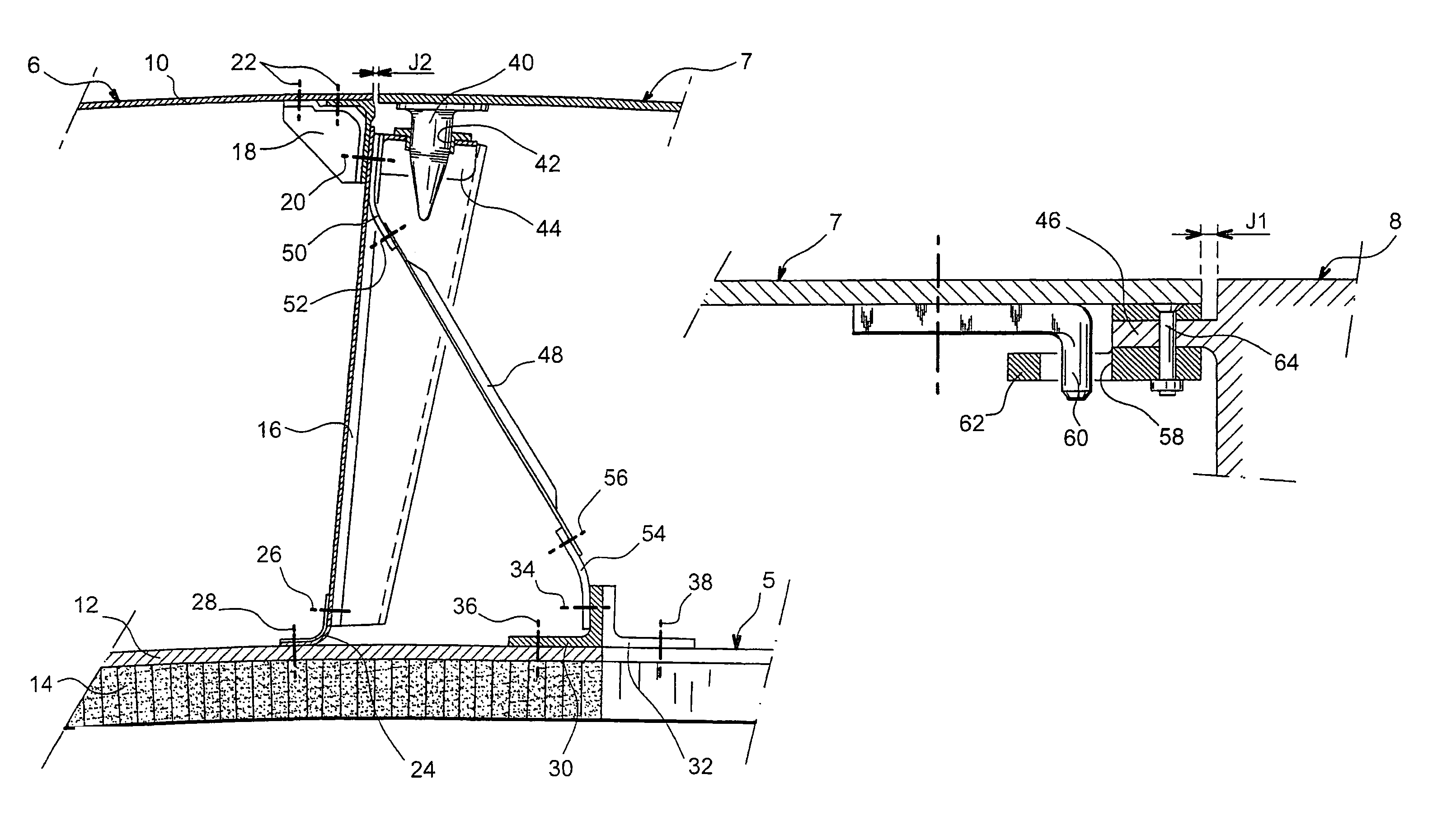
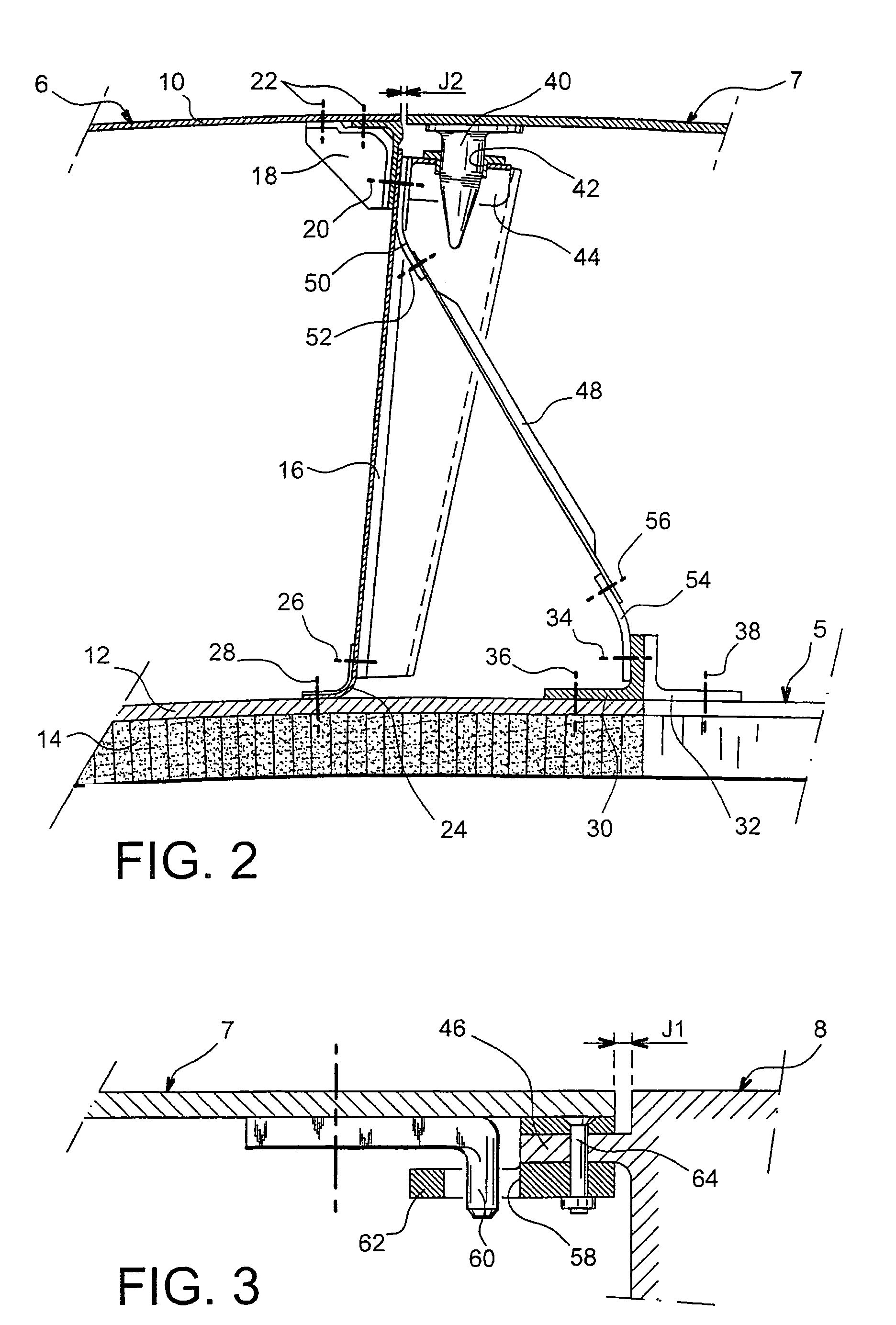
[0017]According to the invention, the additional stiffening means comprise several rigid stiffeners, of which one first end is fixed to the air inlet structure close to the axial force transmission means, and a second end is fixed to the air inlet structure close to the location at which the structure is fixed to the fan casing. Thus, the air inlet structure is reinforced to oppose the suction force that tends to pull this structure forwards.
second embodiment
[0018]According to the invention, the additional stiffening means comprise complementary elements formed on a front edge of the thrust inverter cowl and on a back edge of the fan cowl respectively, the said complementary elements being designed to be inserted one into the other, with a small predetermined axial clearance in the closed position of the fan cowl, to enable transmission of axial forces after compensation of the said clearance. After compensation of the existing clearance between the said complementary elements, this arrangement provides a rigid link between the fan cowls and the thrust inverter cowls to take account of manufacturing tolerances, the said rigid link opposing the suction force that tends to draw the air inlet structure forwards.
[0019]In the second embodiment of the invention, the complementary elements advantageously comprise several orifices formed on the front edge of the thrust inverter cowl and several studs formed on the back edge of the fan cowl, so ...
PUM
 Abstract
Description
Claims
Application Information