Overflow launder

a technology of overflow laundering and overflow, which is applied in the direction of solid separation, feed/discharge of settling tanks, wet separation, etc., can solve the problems of poor separation quality and downward flow, and achieve the effect of reducing horizontal distances and preventing flow interactions

Active Publication Date: 2008-02-26
UNIV OF NEWCASTLE RES ASSOCS
View PDF17 Cites 8 Cited by
  • Summary
  • Abstract
  • Description
  • Claims
  • Application Information

AI Technical Summary

Benefits of technology

[0021]Preferably, the lips of each of the said “v” shaped channels comprising the said secondary troughs intersect the inclined plates in a Reflux Classifier or other inclined or vertical plate device. The inclined or vertical plates extend to a higher elevation than the lips of the secondary troughs, forcing all fluid and particles to report directly to the said secondary troughs. The said intersection produces independent outlets for the fluid and its associated particles, thus preventing flow interactions between different sections of the vessel, and also greatly reducing the horizontal distances along which the fluid and associated particles must travel.

Problems solved by technology

A disadvantage of having the catchment trough around the perimeter of the cell is that particles entrained by the upward flowing fluid must travel laterally with a substantial horizontal motion near the surface of the vessel in order to reach the rim of the separation cell, unless of course they originate from a location near the vessel perimeter.
This is inefficient as the particle must again undergo a separation process so that it can finally reach the rim.
Further disadvantages occur when using overflow launders with a reflux classifier, which is a separate cell that includes a series of inclined parallel plates that allow particular particles to rise to the surface, which may depend on the properties of the particles such as their size or density.
This may produce a downward flow in an included channel or even a blockage.
This interaction may then produce a poorer quality separation.

Method used


Image

  • Overflow launder
  • Overflow launder
  • Overflow launder

Examples


Embodiment Construction

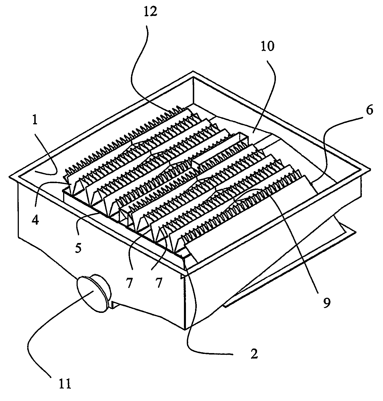
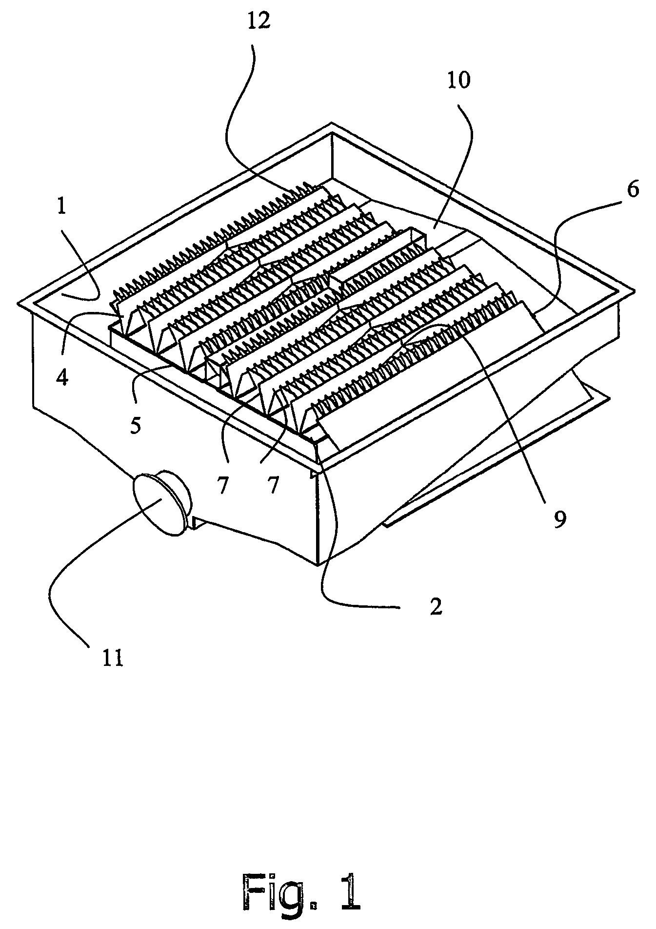
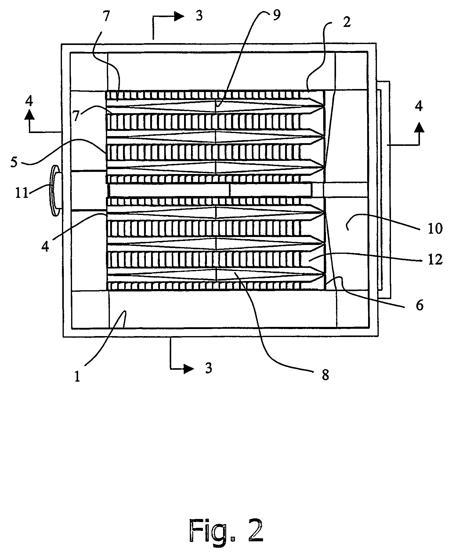
[0031]Referring to the drawings, the overflow launder includes a primary trough 1 surrounding the upper rim 2 of a reflux classifier having an upper set of plates 12. An array of secondary troughs 4 extend across the fluid surface of the reflux classifier from one side 5 of the rim to the opposite side 6 of the rim. This allows fluid to drain from either end of each secondary trough into the primary trough.

[0032]The secondary troughs include a pair of elongate lips 7 forming overflow weirs into the trough 4. The lips of each secondary trough are substantially level, as seen in FIG. 3.

[0033]The secondary troughs are channels that are “v” shaped in cross section. They include a false floor 8 that extends along the channel. The false floor is relatively higher in the centre region 9 of the channel and relatively lower toward each end of the channel. This forms a raised internal portion at an intermediate position in the trough, and relatively lower portions toward each end of the troug...


PUM

PropertyMeasurementUnit
elevationaaaaaaaaaa
perimeteraaaaaaaaaa
hydrophobicaaaaaaaaaa

Abstract

An overflow launder for a separation cell where particles are fluidiZEd and rise to the top of the cell, has a primary trough (1) surrounding the rim of the cell (2), and an array of secondary troughs (4) extending across the fluid surface from the side (5) of the rim to the opposite side (6). FluidiZed particles can report directly to the secondary troughs (4) without travelling across the surface of the cell, reducing the incidence configurations with radial secondary troughs and external and / or internal primary troughs are also described.

Description

CROSS REFERENCE TO RELATED APPLICATION[0001]The present application is a 35 U.S.C. § 371 national phase conversion of PCT / AU2004 / 000444 filed 5 Apr. 2004, which claims priority of Australian Application No. 2003 / 901615 filed 4 Apr. 2003.FIELD OF THE INVENTION[0002]The present invention relates to overflow launders. It has been developed primarily as a device for collecting overflow from a separation cell and will be described hereinafter with reference to this application. However, it will be appreciated that the invention is not limited to this particular field of use.BACKGROUND OF THE INVENTION[0003]Any discussion of the prior art throughout the specification should in no way be considered as an admission that such prior art is widely known or forms part of the common general knowledge in the field.[0004]Known overflow launders include catchment troughs which surround the outer perimeter of a separation cell. A separation cell is typically a device for separating particles via the...

Claims


Application Information

Patent Timeline
Patent Type & Authority Patents(United States)
IPC IPC(8): B01D21/24B03B5/62B03B11/00
CPCB03B5/623B03B11/00
Inventor GALVIN, KEVINMUNRO, MAURICE
Owner UNIV OF NEWCASTLE RES ASSOCS
Why Eureka
Try Eureka