Port array topology for high port count wavelength selective switch

a wavelength selective switch and port array technology, applied in the field of optical switch systems, can solve the problems of not including the practical consideration of requirements, bde's have their own deflection limitations, and the limit of the number of resolvable spots or the total number of ports, so as to reduce the required improvement in the angular range of mems mirrors, increase the allowable packing density, and save spa

Active Publication Date: 2012-11-20
CAPELLA PHOTONICS INC
View PDF20 Cites 4 Cited by
  • Summary
  • Abstract
  • Description
  • Claims
  • Application Information

AI Technical Summary

Benefits of technology

[0043]Nrs=2⁢2⁢⁢θm⁢⁢ax4⁢θo=θm⁢⁢axθo=π⁢⁢ωo⁢θm⁢⁢axλ(6)where θmax is the maximum angle the mirror can turn in each direction. Note that an additional factor of 2 accounts for the angle of the steered beam, which is twice the rotation angle of the mirror. Eq. (6) illustrates the additional restriction of the resolvable spot imposed by the port to port cross talk. When the light beam is moving across the port array, it needs to satisfy the port-to-port cross talk and the hitless requirement simultaneously. This reduces the density of the port array4. Spot Size Requirements for Maximizing the Passband of the WSS
[0065]If the limitation of the MEMS angle is more stringent, one can further reduce its requirements by staggering the columns to increase the packing of the collimators as shown in FIG. 8C. The staggering of the columns can keep the center-to-center distance between ports the same as in the configuration shown in FIG. 8B, but the required lateral movement of the beam can be reduced by a factor of cos 30° if the staggered port columns are in a port packing configuration sometimes referred to as “hexagonal close packed”. In order to maintain the low cross-talk during the switching, the gap between the clusters of fiber collimators should be increased by about 24%. While this may further reduce the density of ports in the columns, it increases the overall density of ports due to the reduced horizontal distance between the columns. The net port density increases slightly, e.g., by about 7%. This enables the 2×N configuration since less micro-mirror rotation is needed about the y axis and less optics area is required. By way of example, the staggered column 2×N port array shown in FIG. 8C can be configured such that the optics area is increased by only 1.5× and the required angular range for the beam reflecting elements is only 1.16θy.

Problems solved by technology

Since there are practical constraints to the total deflection angle there is a limit to the number of resolvable spots or total number of ports.
These BDE's have their own deflection limitations governed by their operating principles.
However, the above analysis does not including the practical consideration of the requirements of the so-called “hitless” switching.
This reduces the density of the port array
However, this may be impractical since the large aspect ratio of the channel mirrors typically gives one rotation axes a larger angular range than the other.
Generally, the larger optical system, the more difficult to design and manufacture.
The optical aberration also goes up when the system etendue is increased.

Method used


Image

  • Port array topology for high port count wavelength selective switch
  • Port array topology for high port count wavelength selective switch
  • Port array topology for high port count wavelength selective switch

Examples


embodiments

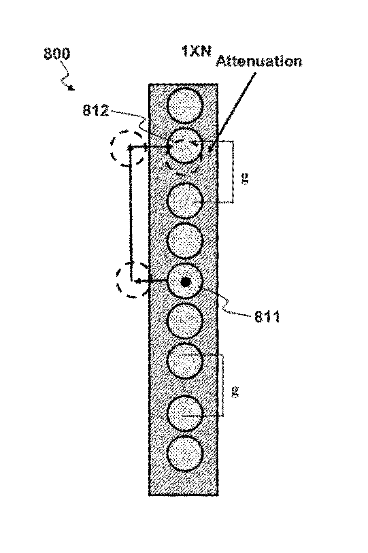
[0056]Given the aforementioned technical considerations the present invention prescribes a unique topology or arrangement of the fiber collimator array to maximize the packing density of the ports for a given angle range of the micro-mirrors with consideration to the number of resolvable spots allowed by performance constraints. The beams positions at the collimator array, as determined by the BDE, are shown in FIGS. 7A-7C. The dashed circle indicates the reflected optical beam. In a “Drop” configuration shown, the center collimator with a dot at the center is the input port for a multi-wavelength beam and the other circles represent collimators or ports where the beams carrying the spectral channels are directed for out-coupling. The lines with arrows indicate the trajectory of the beam due to the angular rotation of the MEMS micro-mirrors as the out-coupling of a given channel is reconfigured from one port to a different port.

[0057]FIG. 7A is similar to FIG. 6, which shows a hitle...


PUM


Abstract

An optical apparatus can include an optical port array having an M×N array of fiber collimator ports. The array of ports is configured such that there is a gap within each column of ports located between two rows of ports. The gap is wide enough to permit a hitless beam switching trajectory to pass between the two rows of ports from one side of the array of ports to an opposite side.

Description

FIELD OF THE INVENTION[0001]This invention generally relates of optical switch systems and more particularly to fiber collimator array or ports of the wavelength selective switch (WSS) to achieve the maximum port count with limited angle ranges of the beam deflecting elements.BACKGROUND OF THE INVENTION[0002]Multi-channel optical signals typically comprise a plurality of spectral channels, each having a distinct center wavelength and an associated bandwidth. The center wavelengths of adjacent channels are spaced at a predetermined wavelength or frequency interval, and the plurality of spectral channels may be wavelength division multiplexed to form a composite multi-channel signal of the optical network. Each spectral channel is capable of carrying separate and independent information. At various locations, or nodes, in the optical network, one or more spectral channels may be dropped from or added to the composite multi-channel optical signal, as by using, for example, a reconfigur...

Claims


Application Information

Patent Timeline
Patent Type & Authority Patents(United States)
IPC IPC(8): G02B6/26
CPCG02B6/3518G02B6/359G02B6/3546G02B6/356
Inventor YANG, LONGGARRETT, MARK H.EHRLICH, JEFFREY E.
Owner CAPELLA PHOTONICS INC
Why Eureka
Try Eureka