Deformation resistant panels

a technology of deformation resistance and panels, which is applied in the field of plastic containers, can solve problems such as container bulging or barreling, and achieve the effects of preventing or reducing the bulging or barreling of containers, increasing the flexing of the sidewalls of vacuum panels, and facilitating the expansion of container pressur

Active Publication Date: 2008-02-26
GRAHAM PACKAGING CO LP
View PDF19 Cites 48 Cited by
  • Summary
  • Abstract
  • Description
  • Claims
  • Application Information

AI Technical Summary

Benefits of technology

[0009]In the case of a horizontal rib, the rib has a depth (in the radial direction of the container) such that the island structure is not completely divided by the rib. In other words, the rib is not coplanar or flush with the surface of the vacuum panel. The rib preferably has a depth such that sufficient island structure exists between the rib and vacuum panel to prevent the rib acting as a hinge between the divided portions of the island. The overall effect of the horizontal rib is to resist the expansion of the outer wall of the container. Bulging or “barreling” is prevented or diminished when the container is subjected to fill pressure at high temperatures. These structural improvements to resist expansion can be used in conjunction with panel technology that allows for increased flexing of the vacuum panel sidewalls so that the pressure on the container may be more readily accommodated. Reinforcing ribs of various types and location may still be used, as described above, to compensate for any excess stress that will inevitably be present from the flexing of the container walls into the new “pressure-adjusted” condition by ambient forces.
[0011]Panel designs in accordance with the invention also (1) improve overall dent resistance due to reduced vacuum pressure resulting from product volume reduction, (2) provide improved label support, and (3) because of reduced vacuum pressure, allow the reduction of container weights, affording an increased number of design options for other container portions.
[0014]Other embodiments of the invention provide a method of reducing deformation in a plastic container. The method includes providing the container with a substantially cylindrical sidewall, providing the container with a base attached to a lower portion of the sidewall, providing a finish attached to an upper portion of the sidewall, and providing a vacuum panel located in the sidewall. The method also includes providing a raised island protruding from the vacuum panel and surrounded by the vacuum panel, cross sectional areas of the island being defined as areas in horizontal planes of the container. The island is provided with an upper portion, a middle portion adjacent to the upper portion, and a lower portion adjacent to the middle portion. A cross sectional area of the middle portion is less than a cross sectional area of the upper portion and less than a cross sectional area of the lower portion.

Problems solved by technology

The expansion results in container bulging or barreling due to the inherent pressure induced during the filling operation.

Method used


Image

  • Deformation resistant panels
  • Deformation resistant panels
  • Deformation resistant panels

Examples


first embodiment

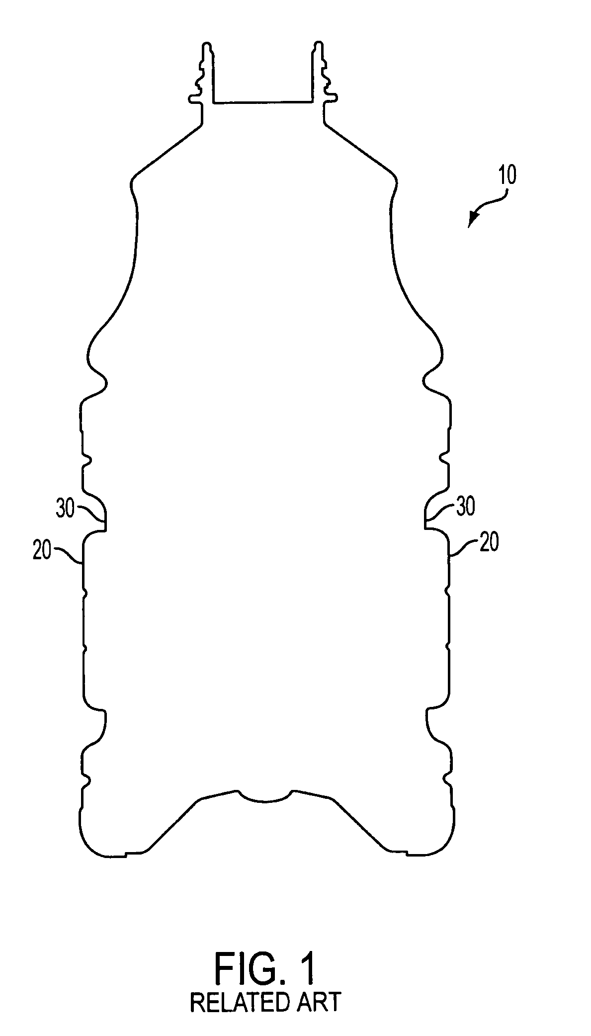
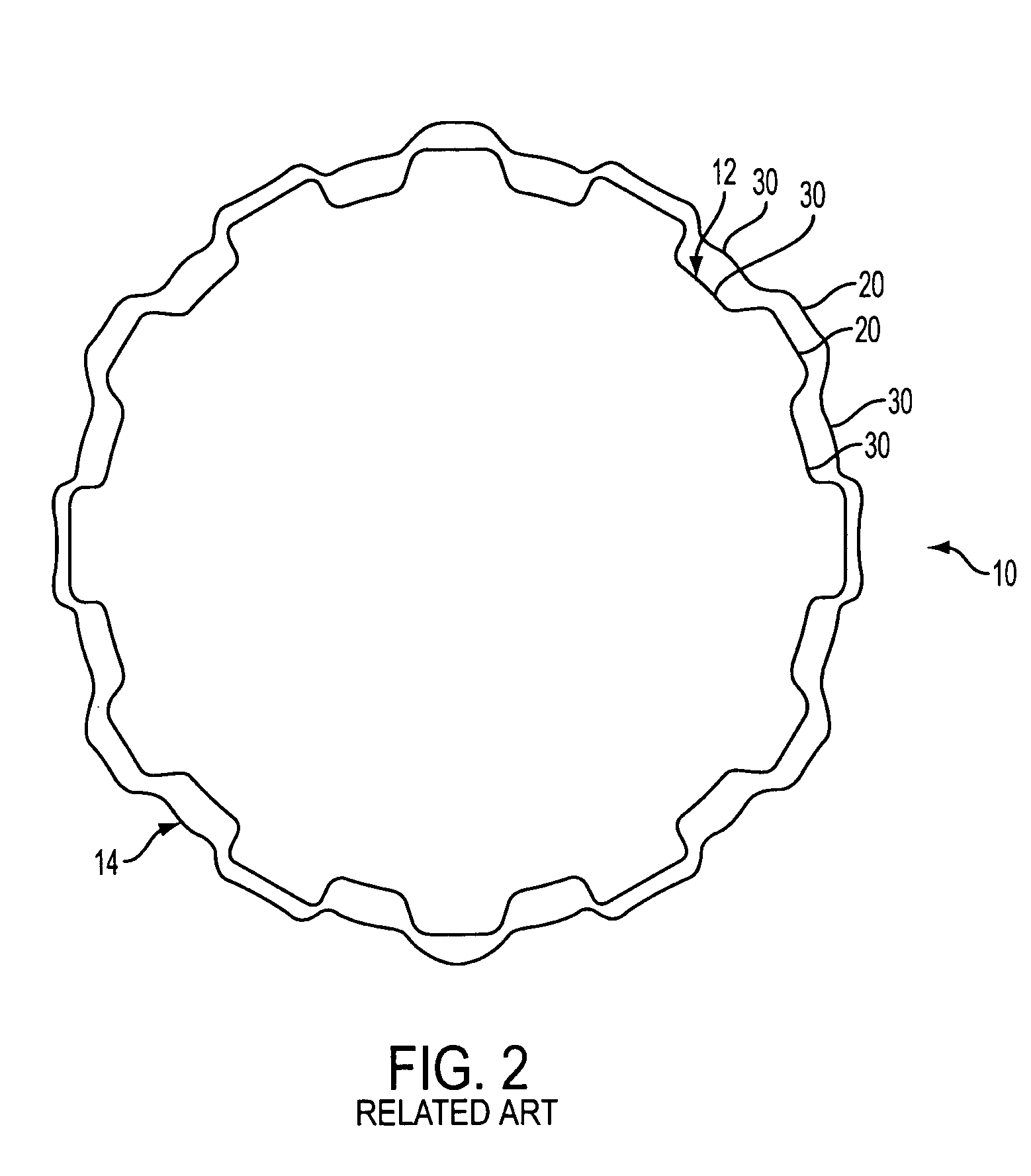
[0029]FIGS. 3-5 show the invention. In this embodiment, a container 100 has a finish 102 for filling and dispensing fluid, a bell 104, a base 106 and a body 110. Body 110 has a generally cylindrical shape and connects base 106 to bell 104. In this example, body 110 has at least one label mounting area 112 that is located between (and includes) an upper label bumper 114 and a lower label bumper 116. A label or labels can be applied to label mounting area 112 using methods that are well known to those skilled in the art, including shrink wrap labeling and adhesive methods. The label can extend around a portion of or the entire label mounting area 112.

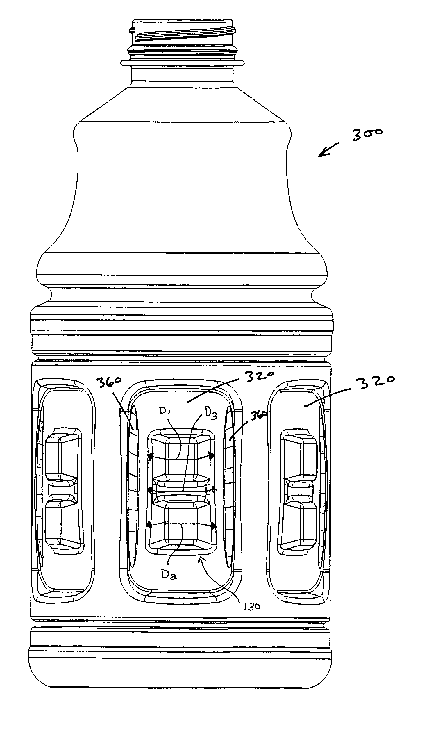
[0030]Disposed within the label mounting area is a series of vacuum panels 120 which, in this example, are symmetrically distributed around body 110. Vacuum panels 120 flex under the pressure of hot filling and subsequent cooling to adjust for pressure changes within container 100. A raised island 130 is located within at least one vacuum...

second embodiment

[0034]FIGS. 6-8 show a container 200 in accordance with the invention in which islands 230 are shaped like a peanut or figure “8”. Each island 230 has a middle portion 234 that has a reduced cross sectional area as compared to an upper portion 232 and a lower portion 236. The cross sectional areas are taken along horizontal planes of container 200. Unlike the example shown in FIGS. 3-5 (where the cross sectional area of middle portion 234 is reduced by reducing its dimension in the radial direction), this embodiment reduces the cross sectional area of middle portion 234 by reducing it dimension in the circumferential direction. In other embodiments, the dimension of middle portion 234 is also reduced in the radial direction. As shown in FIG. 6, a first distance D1 can extend horizontally along the exterior surface of the upper portion 232 of the island 230 between the left and right borders of the island 230. A second distance D2 can extend similarly along the exterior surface of th...


PUM


Abstract

A plastic container is provided. The plastic container has a substantially cylindrical sidewall, a base attached to a lower portion of the sidewall, a finish attached to an upper portion of the sidewall, and a vacuum panel located in the sidewall. The container also has a raised island protruding from the vacuum panel and surrounded by the vacuum panel, cross sectional areas of the island being defined as areas in horizontal planes of the container. The island has an upper portion, a middle portion adjacent to the upper portion, and a lower portion adjacent to the middle portion. A cross sectional area of the middle portion is less than a cross sectional area of the upper portion and less than a cross sectional area of the lower portion.

Description

BACKGROUND OF THE INVENTION[0001]1. Field of the Invention[0002]The present invention relates generally to plastic containers, and more particularly to hot-fillable containers having deformation resistant vacuum panels.[0003]2. Related Art[0004]The use of blow molded plastic containers for packaging “hot fill” beverages is known. In the process of filling a plastic container with hot liquid, pressure or vacuum imposed on the container can result in permanent deformation of the container. The sidewalls of the container can deform as the container is being filled with hot fluids. In addition, the rigidity of the container decreases after the hot fill liquid is introduced into the container. The temperatures employed in these operations can be above the Tg of the plastic used (for example PET), which can result in the deformation becoming permanent. In addition, as the liquid cools, gas that is also in the container shrinks in volume, producing a vacuum in the container.[0005]Hot fill ...

Claims


Application Information

Patent Timeline
Patent Type & Authority Patents(United States)
IPC IPC(8): B65D1/02B65D1/42B65D23/00
CPCB65D1/0223B65D2501/0018Y10S215/90
Inventor BYSICK, SCOTTPRITCHETT, RAYMONDDENNER, JOHN
Owner GRAHAM PACKAGING CO LP
Why Eureka
Try Eureka