Electric connector

a technology of electric connectors and connectors, applied in the direction of coupling contact members, coupling device connections, coupling devices, etc., can solve problems such as synchronous transfers, and achieve the effects of reducing impedance, increasing electric functions, and reducing impedance among conductive terminals

Active Publication Date: 2008-02-26
LOTES
View PDF1 Cites 7 Cited by
  • Summary
  • Abstract
  • Description
  • Claims
  • Application Information

AI Technical Summary

Benefits of technology

[0005]The primary objective of the present invention is to provide an electric connectors by improving a prior art. The electric connector has an insulating body, a plurality of conductive terminals installed in the insulating body. The conductive terminals have a first set of conductive terminals and a second set of conductive terminals. The first set of conductive terminals are made of different materials of the second set of conductive terminals so as to reduce the impedance between the first set of conductive terminals and the second set of conductive terminals. Comparing to prior arts, the present invention can reduce impedance among conductive terminals so as to increase electric functions, because the different conductive terminals are made of different materials.

Problems solved by technology

Therefore, the different impedances will impede synchronous transfers of electric signals so as to disadvantage to increase the electric functions.

Method used


Image

  • Electric connector
  • Electric connector
  • Electric connector

Examples


Embodiment Construction

[0009]In order that those skilled in the art can further understand the present invention, a description will be described in the following in details. However, these descriptions and the appended drawings are only used to cause those skilled in the art to understand the objects, features, and characteristics of the present invention, but not to be used to confine the scope and spirit of the present invention defined in the appended claims.

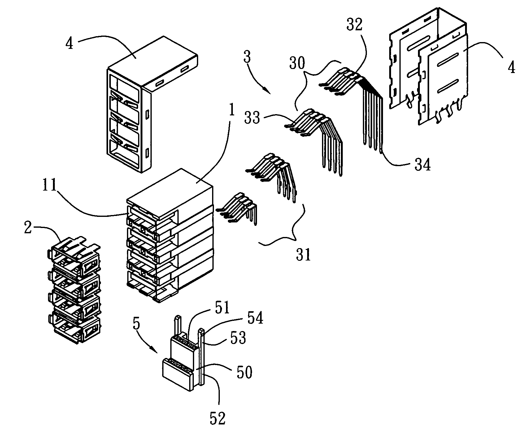
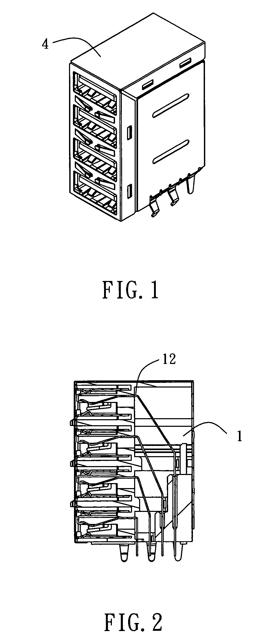
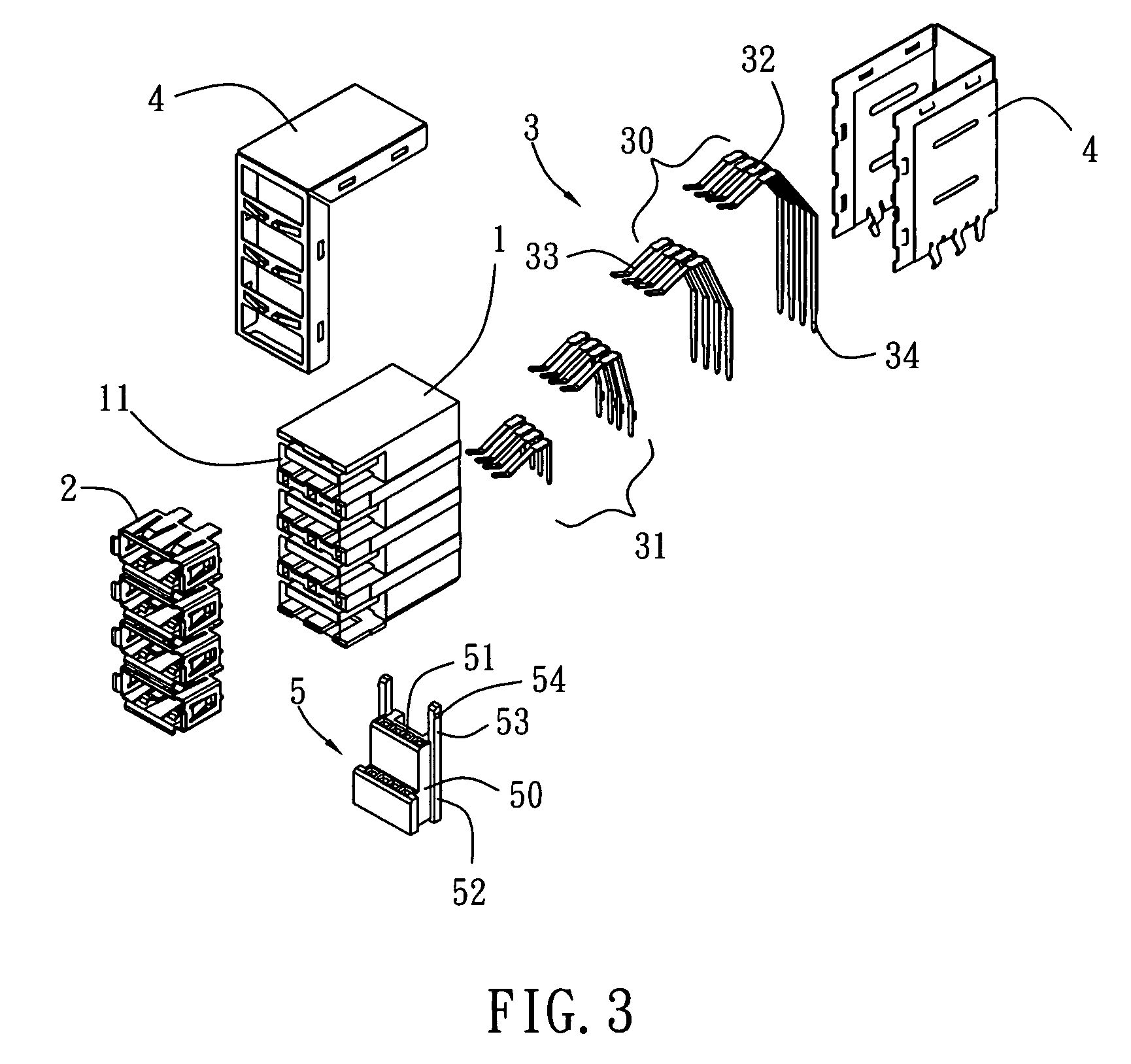
[0010]Referring to FIGS. 1 to 3, the electric connector of the present invention has a plurality of openings 11, an insulating body 1 with a plurality of terminal receiving grooves 12, a plurality of inner shielding casing 2 installed in the openings 11, a plurality of conductive terminals 3 installed into the terminal receiving grooves 12, a outer shielding casing 4 for covering the insulating body 1, and a rear plug 5 installed in the rear of insulating body 1.

[0011]The conductive terminal 3 includes a first set of conductive terminals 30 and a ...


PUM


Abstract

An electric connector has an insulating body, a plurality of conductive terminals installed in the insulating body. The conductive terminals have a first set of conductive terminals and a second set of conductive terminals. The first set of conductive terminals are made of different materials from the second set of conductive terminals so as to reduce the impedance between the first set of conductive terminals and the second set of conductive terminals. The electric connector can reduce impedance among conductive terminals so as to increase electric functions, because the different conductive terminals are made of different materials.

Description

BACKGROUND OF THE INVENTION[0001](a) Field of the Invention[0002]The present invention relates to electric connectors, in particular to an electric connector with a novel devise.[0003](b) Description of the Prior Art[0004]An electric connector of a prior art has an insulating body with a plurality of openings, a plurality of terminal receiving grooves, a plurality of inner shielding casings installed in the openings, a plurality of conductive terminals inserted into the terminal receiving grooves and an outer shielding casing covered on the insulating body. A rear plug serves to prevent from a short circuit caused by self-deformation of the adjacent terminals or stains of dust and dirt. The rear plug serves also to position properly the end of the terminals firmly aiming for an electric circuit. However, because the conductive terminals of the electric connectors of the prior art are usually made of the same materials (usually compound copper), such as compound of phosphorous-copper...

Claims


Application Information

Patent Timeline
Patent Type & Authority Patents(United States)
IPC IPC(8): H01R13/648
CPCH01R13/514H01R23/688Y10S439/941H01R13/659H01R13/6586H01R13/6474
Inventor JU, TED
Owner LOTES
Why Eureka
Try Eureka