Reflective type continuous domain in-plane switching liquid crystal display

a liquid crystal display and continuous domain technology, applied in non-linear optics, instruments, optics, etc., can solve the problems of increased cost of tn mode lcd, narrow viewing angle, and inability to eliminate hereditary drawbacks, etc., and achieve the effect of small color shi

Inactive Publication Date: 2008-02-26
INNOLUX CORP
View PDF14 Cites 0 Cited by
  • Summary
  • Abstract
  • Description
  • Claims
  • Application Information

AI Technical Summary

Benefits of technology

[0011]An object of the present invention is to provide a multi-domain reflective type IPS liquid crystal display which has a relatively small color shift.

Problems solved by technology

Even though TN mode LCDs have been put into use in many applications, they have an inherent drawback that cannot be eliminated; namely, a very narrow viewing angle.
However, the cost of the TN mode LCD is increased.
When this single domain IPS technology is applied in a reflective type liquid crystal display, color shift is likewise a problem.

Method used


Image

  • Reflective type continuous domain in-plane switching liquid crystal display
  • Reflective type continuous domain in-plane switching liquid crystal display
  • Reflective type continuous domain in-plane switching liquid crystal display

Examples


first embodiment

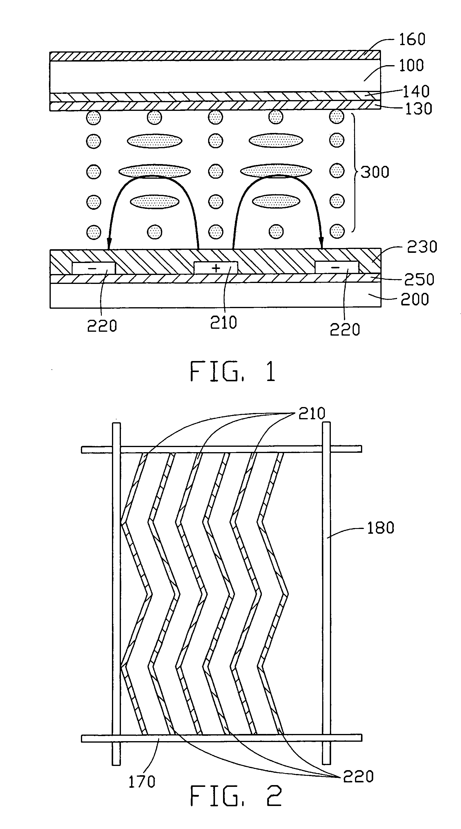
[0024]Referring to FIG. 1 and FIG. 2, these are respectively a side cross-sectional view of a reflective type in-plane switching liquid crystal display (IPS LCD) according to the present invention and a plan view of a pixel region of the IPS LCD. This IPS LCD comprises a transparent upper substrate 100, a lower substrate 200, and positive liquid crystal molecules 300 interposed between the upper and lower substrates 100, 200. An upper polarizer 160 is disposed on the outer side of the upper substrate 100, a color filter 140 is disposed on an underside of the upper substrate 100, and an upper alignment film 130 is disposed on an underside of the color filter 140. A reflection layer 250 is formed on the lower substrate 200. A plurality of gate lines 170 and data lines 180 are disposed on the lower substrate 200, and define a plurality of pixel regions arranged in a matrix. Each pixel region comprises a plurality of pixel electrodes 210 and a plurality of common electrodes 220. The pix...

second embodiment

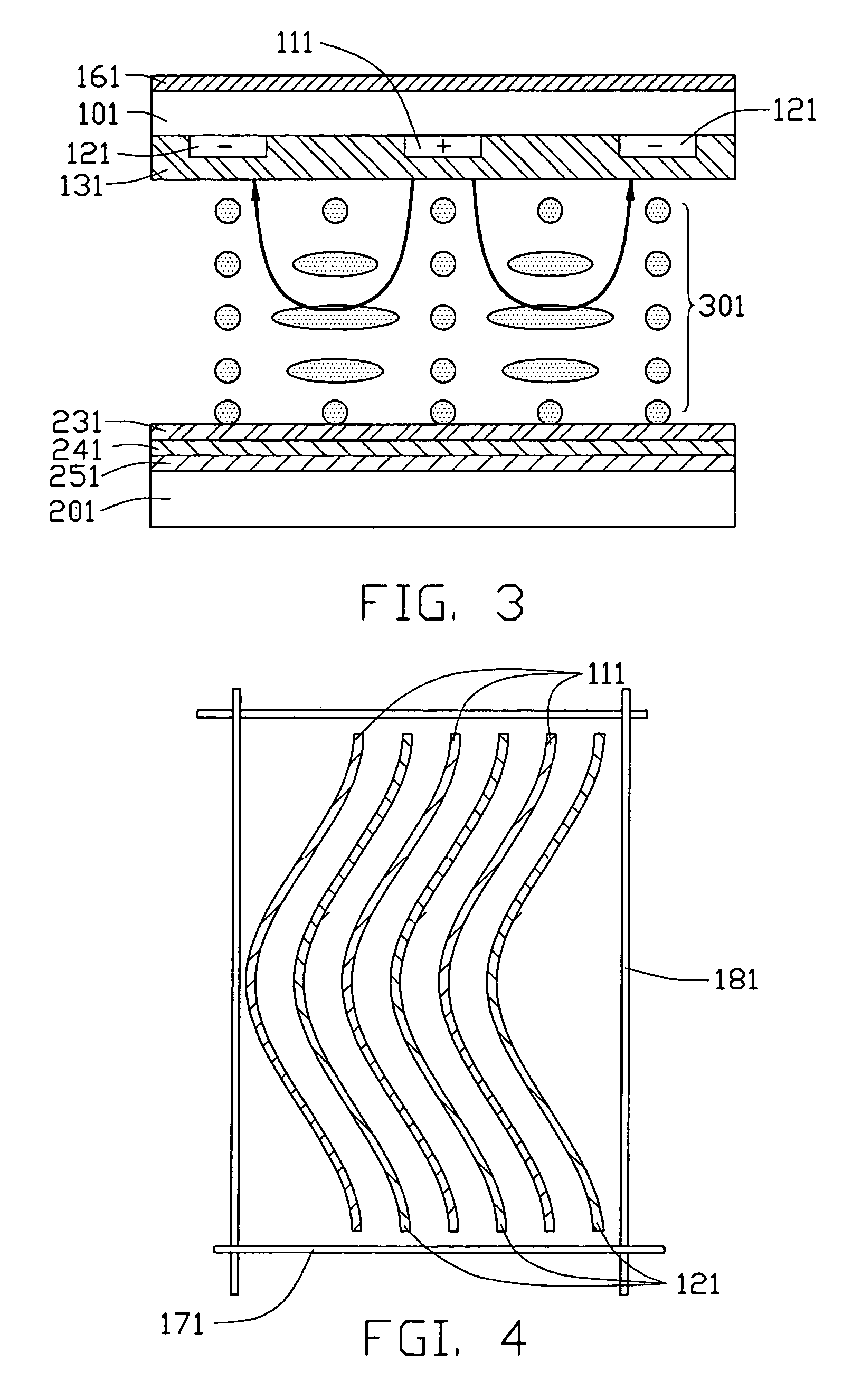
[0026]Referring to FIG. 3 and FIG. 4, a reflective type in-plane switching liquid crystal display (IPS LCD) according to the present invention comprises a transparent upper substrate 101, a lower substrate 201, and positive liquid crystal molecules 301 interposed between the upper and lower substrates 101, 201. A lower alignment film 231, a color filter 241 and a reflection layer 251 are stacked on the lower substrate 201 in that order from top to bottom. An upper polarizer 161 is disposed on an outer side of the upper substrate 101. A plurality of gate lines 171 and data lines 181 are disposed on the upper substrate 101, and define a plurality of pixel regions arranged in a matrix. Each pixel region comprises a plurality of pixel electrodes 111 and a plurality of common electrodes 121. The pixel electrodes 111 and the common electrodes 121 have a similar arcuate configuration, and are uniformly spaced apart from each other. An upper alignment film 131 is disposed on the electrodes ...

third embodiment

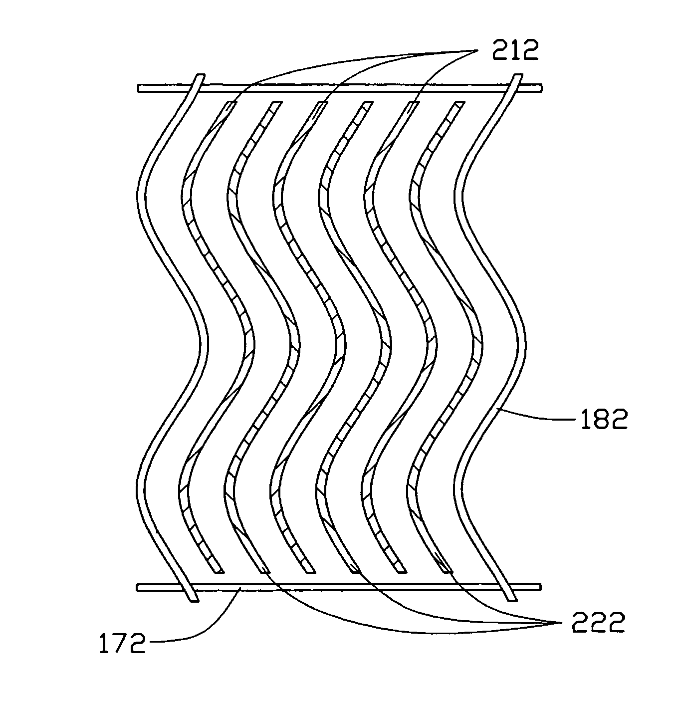
[0028]Referring to FIG. 5 and FIG. 6, a reflective type in-plane switching liquid crystal display (IPS LCD) according to the present invention comprises a transparent upper substrate 102, a lower substrate 202, and positive liquid crystal molecules 302 interposed between the upper and lower substrates 102, 202. An upper polarizer 162 and a lower polarizer 262 are disposed on outer sides of the substrates 102, 202 respectively. A color filter 142 is disposed on an underside of the upper substrate 102, and an alignment film 132 is disposed on an underside of the color filter 142. A reflection layer 252 is disposed on an outer side of the lower alignment film 262. The lower substrate 202 is transparent, so as to let light beams pass through and reach the reflection layer 252. A plurality of gate lines 172 and data lines 182 are formed on the lower substrate 202, and define a plurality of pixel regions arranged in a matrix. Each pixel region comprises a plurality of pixel electrodes 212...


PUM

PropertyMeasurementUnit
refractive indexaaaaaaaaaa
opticalaaaaaaaaaa
electrical anisotropyaaaaaaaaaa

Abstract

A reflective type IPS LCD includes a transparent upper substrate (100) and a lower substrate (200), and liquid crystal molecules (300) interposed between the substrates. A reflection layer (250) is disposed on the lower substrate. A plurality of gate lines (170) and a plurality of data lines (180) are formed on the upper substrate, thereby defining a plurality of pixel regions arranged in a matrix. Each pixel region includes pixel electrodes (210) and common electrodes (220). The pixel electrodes and the common electrodes have a bent configuration, and are spaced apart from each other. Therefore the electric field generated by them is along two directions, and the LCD exhibits a two-domain display effect. When viewing the LCD display from any oblique angle, the color shifts generated by the two domains counteract, and thus the overall color shift of the display is small.

Description

BACKGROUND OF THE INVENTION[0001]1. Field of the Invention[0002]The present invention relates to a reflective type IPS (in-plane switching) mode LCD (liquid crystal display), and the control of liquid crystal molecules therein.[0003]2. Description of Prior Art[0004]A liquid crystal display utilizes the optical and electrical anisotropy of liquid crystal molecules thereof in order to produce an image. The liquid crystal molecules have a particular passive orientation when no voltage is applied thereto. However, in a driven state, the liquid crystal molecules change their orientation according to the strength and direction of the driving electric field. A polarization state of incident light changes when the light transmits through the liquid crystal molecules, due to the optical anisotropy of the liquid crystal molecules. The extent of the change depends on the orientation of the liquid crystal molecules. Thus, by properly controlling the driving electric field, an orientation of the...

Claims


Application Information

Patent Timeline
Patent Type & Authority Patents(United States)
IPC IPC(8): G02F1/1343G02F1/1335
CPCG02F1/134363
Inventor YANG, CHIU-LIENPANG, JIA-PANGCHEN, CHUEH-JU
Owner INNOLUX CORP
Why Eureka
Try Eureka