Valve with adjustable stop

a technology of valve stop and adjustable stop, which is applied in the direction of diaphragm valve, engine diaphragm, machine/engine, etc., can solve the problems of common failure of the actuator, and achieve the effect of increasing the cycle life of the actuator and preventing over-travel of the actuator piston or the valve diaphragm

Inactive Publication Date: 2008-03-04
SWAGELOK CO
View PDF56 Cites 36 Cited by
  • Summary
  • Abstract
  • Description
  • Claims
  • Application Information

AI Technical Summary

Benefits of technology

[0003]The present invention is directed to an adjustable mechanism for limiting movement of a valve or actuator. The adjustable mechanism cooperates with one or more pistons to determine the axial distance the diaphragm will travel. By limiting the distance the piston(s) and diaphragm travel, the cycle life of the actuator is increased and the flow of the fluids within the valve can be regulated. For example, a trickle vale or a mixing valve can be formed. In addition, the stroke of the actuator can be set to match the stroke of the valve diaphragm, thereby preventing over-travel of the actuator piston or valve diaphragm. In some embodiments, the adjustable mechanism for limiting movement of a valve or actuator is accessible from the outside of the valve assembly, thereby avoiding the need to disassemble the valve assembly or any portion thereof to make adjustments.

Problems solved by technology

When evaluating a valve assembly for maximizing valve cycle life, a common failure occurs in the actuator.

Method used


Image

  • Valve with adjustable stop
  • Valve with adjustable stop
  • Valve with adjustable stop

Examples


first embodiment

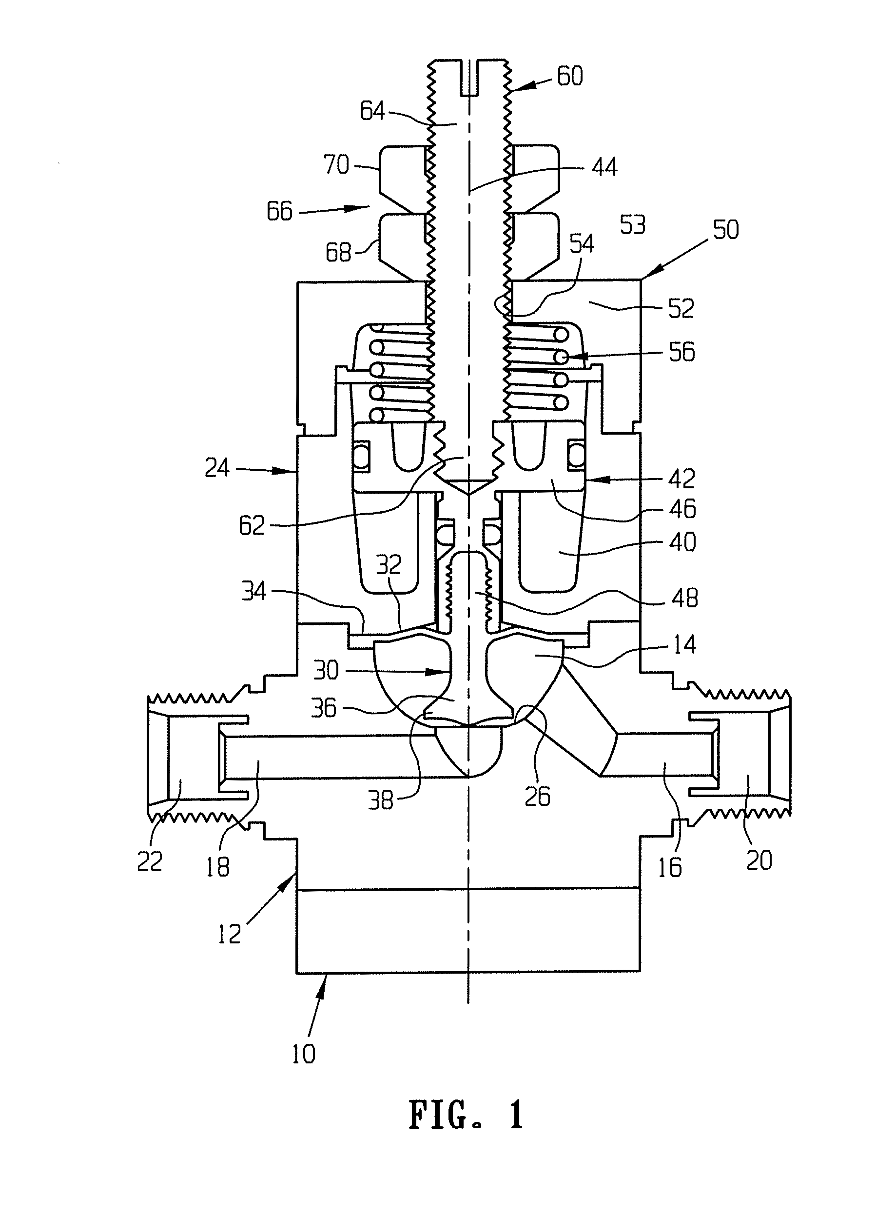
[0019]FIG. 1 illustrates a valve 10 constructed in accordance with the invention. The valve 10 includes a valve body or base 12. The valve base 12 defines a valve chamber 14 that is connected by first and second passages 16 and 18 to first and second ports 20 and 22, respectively, of the valve 10. The base 12 has a valve seat 26 that is located at the inner terminus of the second passage 18. A housing 24 is secured to the base 12 adjacent the valve chamber 14. Typically, fluid flows into the valve 10 through the first passage 18 and out through the second passage 16. The flow path through the valve 10 could be reversed when required in some applications. Additionally, as would be appreciated by one skilled in the art, the valve 10 can have other configurations and such valves can incorporate the adjustable stroke features described herein below. The invention is thus not limited to diaphragm valves.

[0020]A valve member 30 is disposed in the valve chamber 14. The valve member 30 can ...

second embodiment

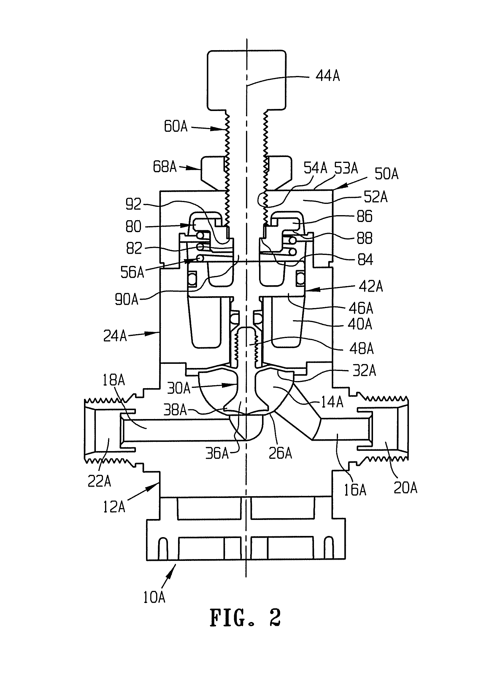
[0027]FIG. 2 illustrates a valve 10a constructed in accordance with the invention. The valve 10a is similar in construction to the valve 10 (FIG. 1). Parts of the valve 10a that are the same as or similar to corresponding parts of the valve 10 are given the same reference numerals with the suffix “a” attached.

[0028]The valve 10a includes a valve base 12a, a housing 24a, and a valve member 30a. The valve 10a also includes a cylinder 40a and a piston 42a supported in the cylinder for sliding movement relative to the housing 24a along a longitudinal central axis 44a of the valve. The valve member 30a is threadedly secured to the piston 42a. A cap 50a is secured to the housing 24a opposite the valve base 12a. The cap 50a closes the upper end of the cylinder 40a. The cap 50a has an annular end wall that has an internally threaded central opening 54a.

[0029]The valve 10a includes a spring seat 80. The spring seat 80 is formed as a separate member from the cap 50a and is movable relative t...

third embodiment

[0035]FIGS. 3-7 illustrate a valve 100 constructed in accordance with the invention. The valve 100 (FIG. 3) includes a valve base 101. The valve base 101 defines a first valve chamber 102 that is connected by a first passage 104 to a first port 106. The valve base 101 defines a second valve chamber 108 that is connected by a second passage 110 to a second port 112. The valve base 101 also defines a connecting passage 114 that extends between and connects the first valve chamber 102 in fluid communication with the second valve chamber 108. The connecting passage 114 terminates in a first outlet opening 116 into the first valve chamber 102 and a second outlet opening 118 into the second valve chamber 108. The first valve chamber 102 has a first valve seat 120 that extends around the first outlet opening 116 into the first valve chamber. The second valve chamber 108 has a second valve seat 122 that extends around the second outlet opening 118 into the second valve chamber. The second v...


PUM


Abstract

An adjustable mechanism for a valve or actuator is provided. The adjustable mechanism cooperates with one or more pistons, which in turn cooperates with a valve element to limit the axial displacement of the valve element relative to the valve seat. The adjustable mechanism can be adjusted axially, thereby providing a greater or lesser distance for the piston and diaphragm to travel. Embodiments incorporating the adjustable mechanism include a trickle valve, an on / off valve and a mixing valve. The adjustable mechanism also provides to the adjustment of the piston stroke to match or closely mirror the stroke of the vale element.

Description

CROSS REFERENCE TO RELATED APPLICATIONS[0001]This application is claims the benefit of U.S. Provisional Application Nos. 60 / 452,772 and 60 / 481,904 filed Mar. 7, 2003 and Jan. 16, 2004, respectively, the entire disclosures of which are hereby incorporated by reference.BACKGROUND OF INVENTION[0002]Many diaphragm valves utilize pneumatic actuation to control whether the valve is opened or closed. A typical actuator contains one or more pistons that are coupled to a valve diaphragm to move the diaphragm against a valve seat to close the valve. Valves can be normally closed or normally opened. In a normally closed valve, a spring biases the piston and thus the diaphragm against the valve seat to maintain it closed. To open the valve, air pressure is fed into the actuator and acts on the piston face(s) such as to move the piston against the spring force. As the actuator piston moves, it disengages the diaphragm from the valve seat thereby opening the valve to flow. In prior art actuators,...

Claims


Application Information

Patent Timeline
Patent Type & Authority Patents(United States)
IPC IPC(8): F16K31/22F15B15/24F16K7/14F16K11/048F16K31/122F16K41/12
CPCF16K7/14F16K11/048F16K31/1221F16K41/12Y10T137/86759Y10T137/86895F16K31/122
Inventor BROWN, RONNIEDELISIO, CARMEN J.SCHEFFEL, GARYSTEDMAN, DAVIDTIMKO, JARED
Owner SWAGELOK CO
Why Eureka
Try Eureka