Top feed of control lines to a reciprocating spider

a technology of control line and reciprocating spider, which is applied in the direction of drilling pipes, well accessories, drilling casings, etc., can solve the problems of loss or impairment of data transfer from downhole instruments, control lines secured to pipe strings are subject to damage and become useless, and the gate of the control line is selected and the effect of sliding engagement and coupling

Inactive Publication Date: 2008-03-04
FRANKS INT
View PDF24 Cites 27 Cited by
  • Summary
  • Abstract
  • Description
  • Claims
  • Application Information

AI Technical Summary

Benefits of technology

[0018]In one embodiment, a passage within the spider body may receive an elongated control line sleeve for containment and protection of one or more control lines from pinching or crushing between slips, or between slips and the pipe string secured by the slips. The elongated control line sleeve has an opening at each end is also received and may be secured within the spider body with one opening disposed upwardly and the other opening disposed downwardly. The control line sleeve may assist in directing and positioning the control lines along the pipe for coupling thereto. Optionally, the sleeve may be secured to any structural member and suspended or supported within the spider. Alternatively, the sleeve may be secured directly to the spider, such as the tapered bowl of the spider or the spider door. The sleeve must also be selectively openable, such as with a slot in one side, in order to receive a control line or to permit the withdrawal of a control line.
[0020]In an alternate embodiment, the spider has a control line passage formed therein by disposing a slidable or selectively positionable control line gate between the pipe string and one of the spider door or the spider body so that the control lines are retained within the control line passage. The control line gate is positionable to form the control line passage even with the pipe string extending through the spider and with the spider door closed. This selective positionability of the control line gate provides a major operational advantage in that a control line can be run through the spider and protected from the pipe string and the slips without having to open the spider door. Accordingly, the control line gate may be positioned while the pipe string is being supported by either the lift elevator or the spider.
[0021]The control line gate is preferably positioned by inserting it with one side facing the pipe string and another side facing the contained control lines and at least one of the spider body or the spider door, or a combination of both. The control line gate is preferably also inserted from the top. After insertion, the control line gate is secured in position. The control line gate is preferably secured to the spider body, the spider door, or a combination thereof. Alternatively, the control line gate may be secured or suspended in position from some other structure, such as an assembly securing the control line guides. In a most preferred embodiment, the control line gate has two edges that are slidingly received in a pair of slots formed in the inner face of the spider body or the spider door so that the control line gate can be lifted out of the slots for receiving an additional control line within the passage and then reinstalled into the slots with all the control lines retained in the passage. As used herein, a “slot” may refer to a slot, track, guide, ridge or any feature that facilitates sliding engagement and coupling.
[0023]The method and apparatus of the present invention allows one or more control lines to be secured along the length of a pipe string as the pipe string is being made up and run into a well. The method and apparatus of the present invention allows control lines to be secured to a pipe string above the rig floor and below the spider, but eliminates the need for an elevated work platform strong enough to support the enormous weight of the pipe string. The method and apparatus of the present invention improves rig safety and operation by top-feeding the control line through the spider and preventing impairment of escape routes on the rig floor.
[0025]According to the presently preferred embodiment, a control line is provided to the pipe string from above the spider. Preferably, the spool may be positioned at a remote location on the rig floor and the control line passed up and over an elevated sheave or pulley so as to come downwardly to the spider. The spool may be rotatably mounted in a fixed location that is a sufficient distance above the spider and in sufficient proximity of the axial centerline of the pipe string to provide a favorable approach angle. The control line should not be bent or deflected at an angle exceeding manufacturer recommendations as the control line is fed downwardly to and into the spider. Preferably, the angle formed between the control line and the pipe string will not exceed about 60 degrees, and more preferably, will not exceed about 45 degrees. Rollers, pulleys or sheaves may be used to limit localized bending of the control line. The control line may be routed or threaded over a roller guide secured above the spider to strategically direct the top-fed control line from the spool through the spider and along the length of the pipe string so that the control line can be secured to the pipe string. The control line is secured to the pipe string with fasteners, such as clamps, sleeves, bands, clips or other fasteners at a position beneath the elevated spider, but in the adjacent area of the rig floor. The control line may be secured along the outer surface of the pipe string at any radial or circumferential location of the pipe string below the spider, but the control line is preferably secured along the outer surface of the pipe string at a radial or circumferential location that is generally aligned with the passage through the spider. Accordingly, the control line passes through the spider without being damaged by the pipe slips within the internal bore of the spider.

Problems solved by technology

Control lines secured to pipe string are subject to being damaged and made useless if pinched or crushed by pipe slips used to grip and support the pipe string, such as during the process of making up the pipe string and running it into the well.
If a control line becomes pinched or trapped between the pipe slips of the spider and the outer surface of the pipe string, or if a control line is pinched between adjacent segments of the pipe slips as they move around and radially inwardly to contact the pipe string, the control line may be damaged and surface control of downhole devices or data transfer from downhole instruments may be lost or impaired.
One problem with the method and apparatus for installing control lines described in the '664 Patent is that the control lines and spools themselves take up a significant area of the rig floor and present an obstacle to various operations.

Method used


Image

  • Top feed of control lines to a reciprocating spider
  • Top feed of control lines to a reciprocating spider
  • Top feed of control lines to a reciprocating spider

Examples


Embodiment Construction

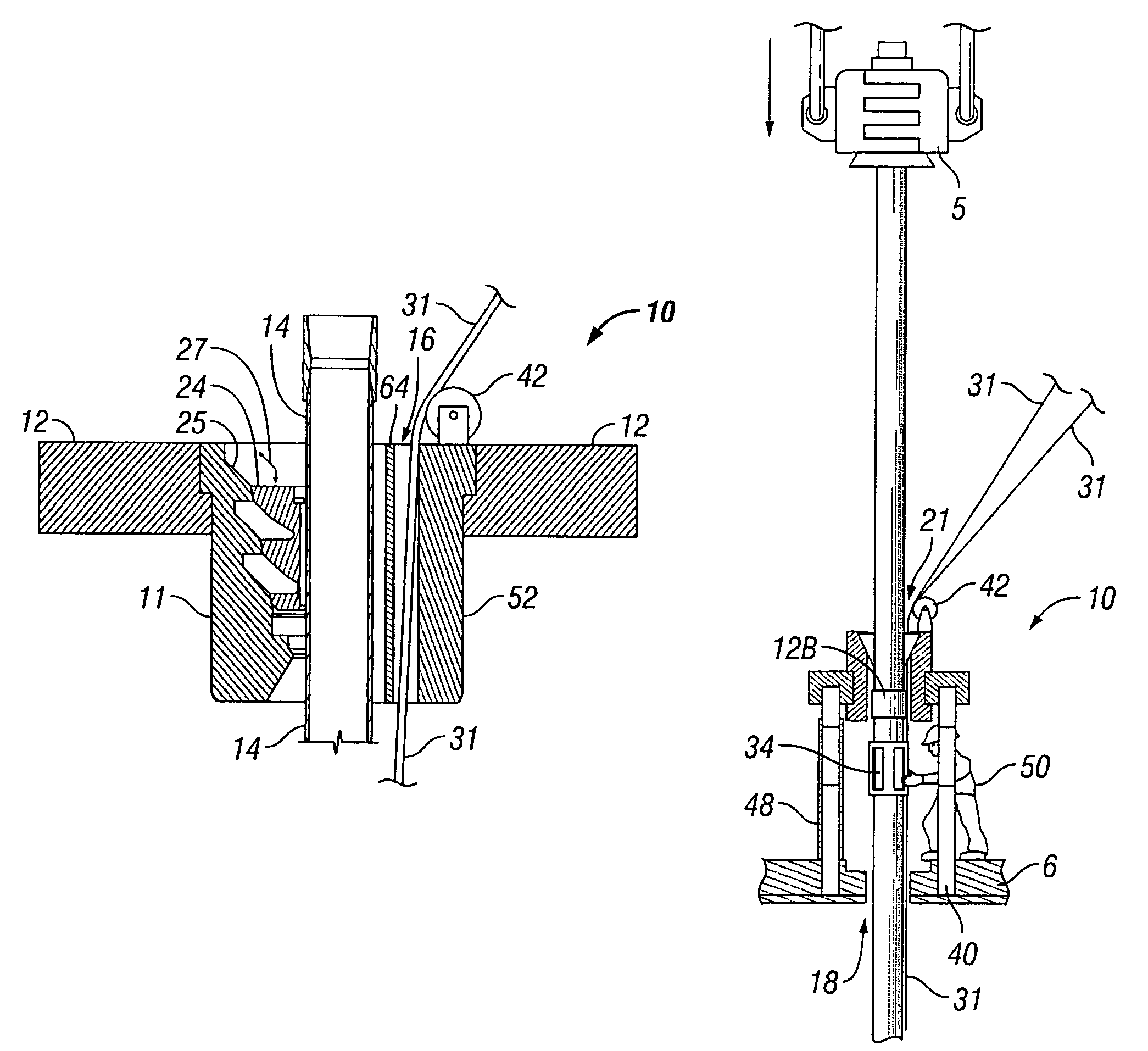
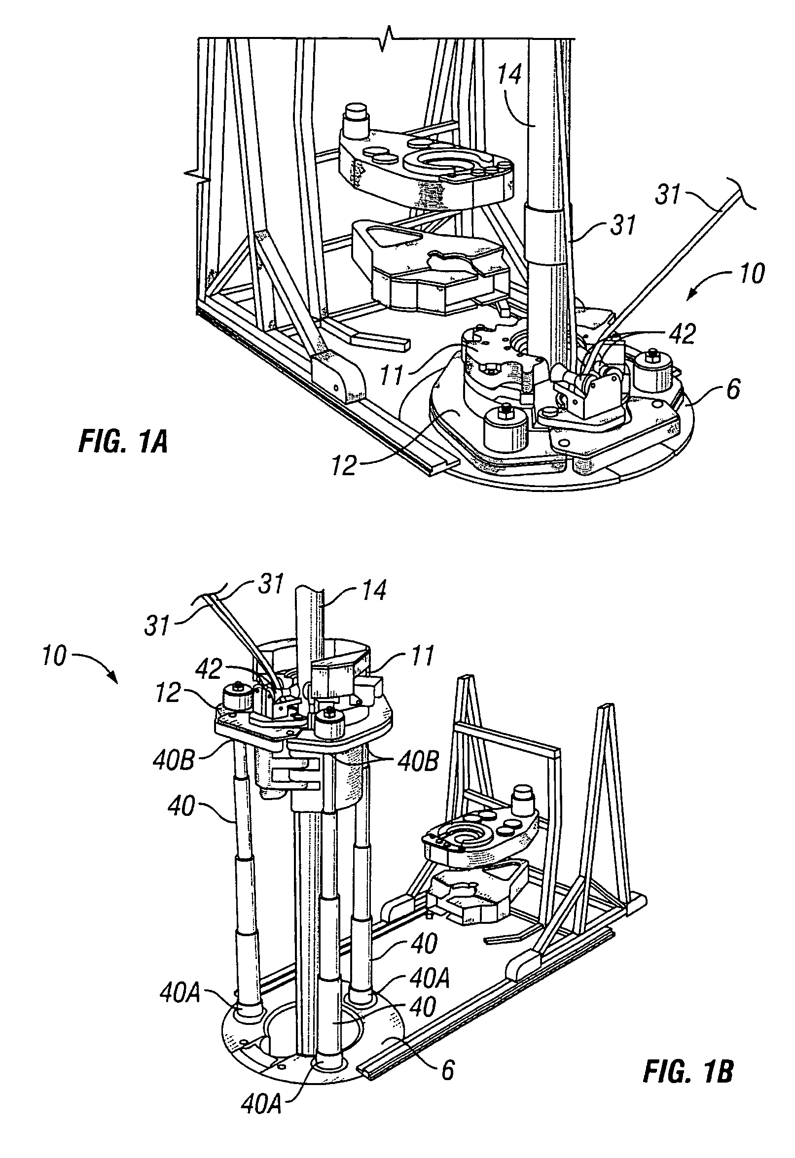
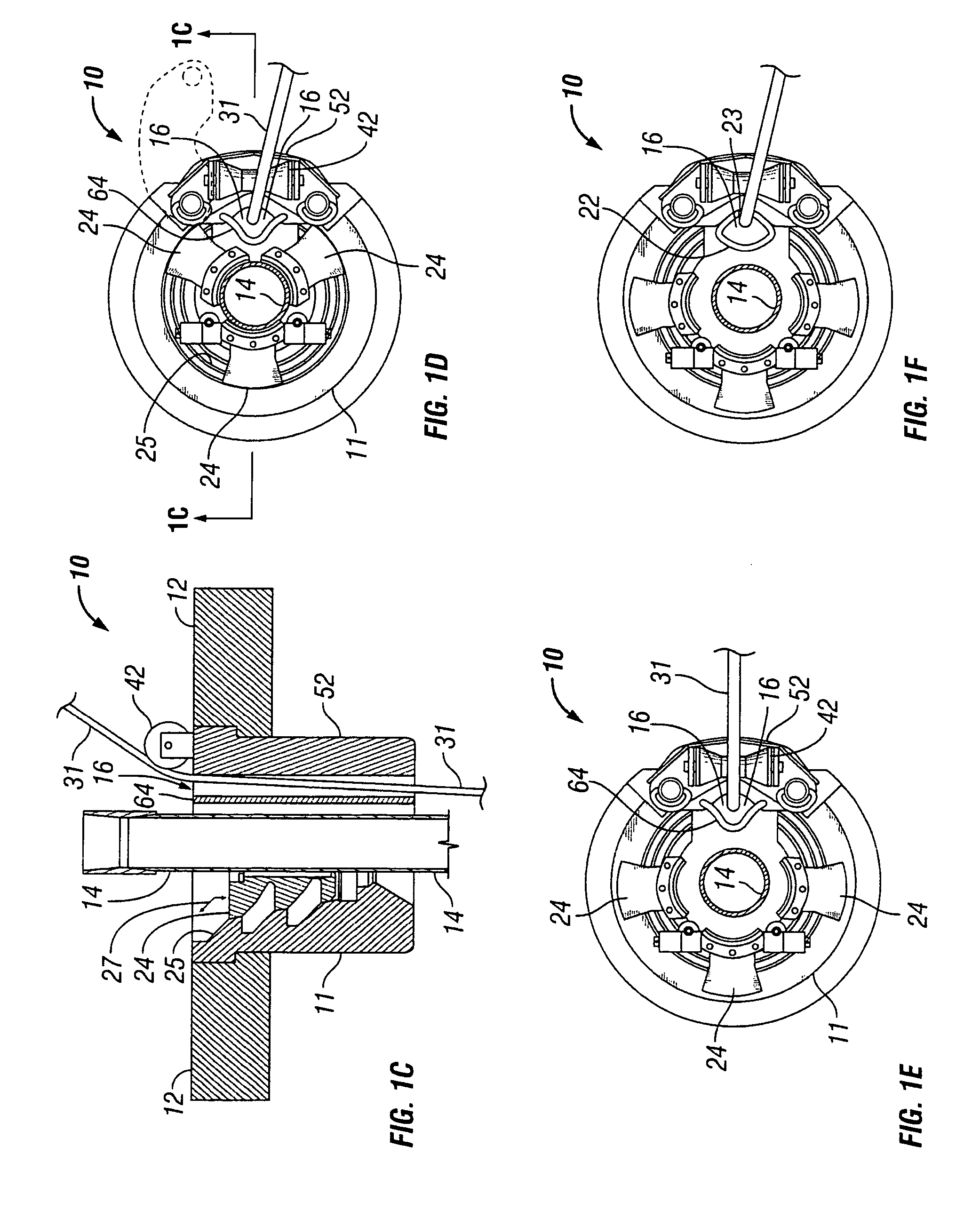
[0045]FIG. 1A is a perspective view of one embodiment of a vertically reciprocating spider assembly 10 in its floor position with a spider 11 received in a reciprocating retainer 12 and control line guides 42 directing top-fed control lines 31 through the spider and downwardly along the length of the pipe string 14. The retainer 12 may be integral with the spider 11 or it may be a separate device adapted to supportably receive the spider 11.

[0046]FIG. 1B is a perspective view of the vertically reciprocating spider assembly 10 supporting the spider 11 in an elevated position to facilitate fastening of the control lines 31 to the pipe string 14. The retainer 12 is supportable with three hydraulically powered telescoping legs 40 angularly distributed around the periphery of the retainer 12 for even support. Any number of legs may be used so long as the spider is stable and the legs 40 do not significantly impede access to the pipe string for fastening the control lines. The legs 40 are...


PUM


Abstract

Method and apparatus for installing control lines and pipe into a well. The pipe-holding spider that is normally mounted on the rig floor is supportably retained in a vertically movable retainer. The retainer is adapted for controllably elevating the spider above the rig floor when the pipe slips within the spider are not engaged with the outer surface of the pipe string, thereby providing personnel access to a portion of the length of the pipe string below the elevated spider and above the rig floor. Personnel are provided with access to the pipe string for applying a fastener to secure the control line to the pipe string. The control line is supplied from above the spider and is positioned by a control line guide supported on the spider or retainer to pass through the spider outside the path of pipe gripping members within the spider.

Description

[0001]This application is a continuation-in-part of U.S. patent application Ser. No. 11 / 114,630 filed on Apr. 26, 2005 now abandoned, which is a continuation of U.S. patent application Ser. No. 10 / 278,718 filed Oct. 23, 2002, now U.S. Pat. No. 6,889,772.BACKGROUND OF THE INVENTION[0002]1. Field of the Invention[0003]The present invention relates to a method and apparatus for installing pipe and a control line in a well. More specifically, the present invention relates to a method and apparatus for securing a control line to a string of pipe as the pipe is being made up and run into a well.[0004]2. Background of the Related Art[0005]Wells are generally drilled deep into the earth's crust to establish fluid communication between the surface and sub-surface geologic formations containing naturally occurring hydrocarbon deposits, such as oil or gas. A well provides a fluid conduit allowing subsurface deposits of oil and gas to be produced at the surface. It is common for a drilled boreh...

Claims


Application Information

Patent Timeline
Patent Type & Authority Patents(United States)
IPC IPC(8): E21B19/02
CPCE21B17/026E21B19/10E21B19/22E21B19/07
Inventor BUYTAERT, JEANSPADONI, LUCIANOSINCLAIR, EDWARDBEGNAUD, BRIAN DAVIDWEBRE, CHARLES MICHAEL
Owner FRANKS INT
Why Eureka
Try Eureka