
Elevator car with lowerable roof

a technology of elevator cars and roofs, which is applied in the direction of elevators, building lifts, transportation and packaging, etc., can solve problems such as damage to elevator cars

Inactive Publication Date: 2008-03-04
INVENTIO AG
View PDF7 Cites 9 Cited by
  • Summary
  • Abstract
  • Description
  • Claims
  • Application Information

AI Technical Summary

Benefits of technology

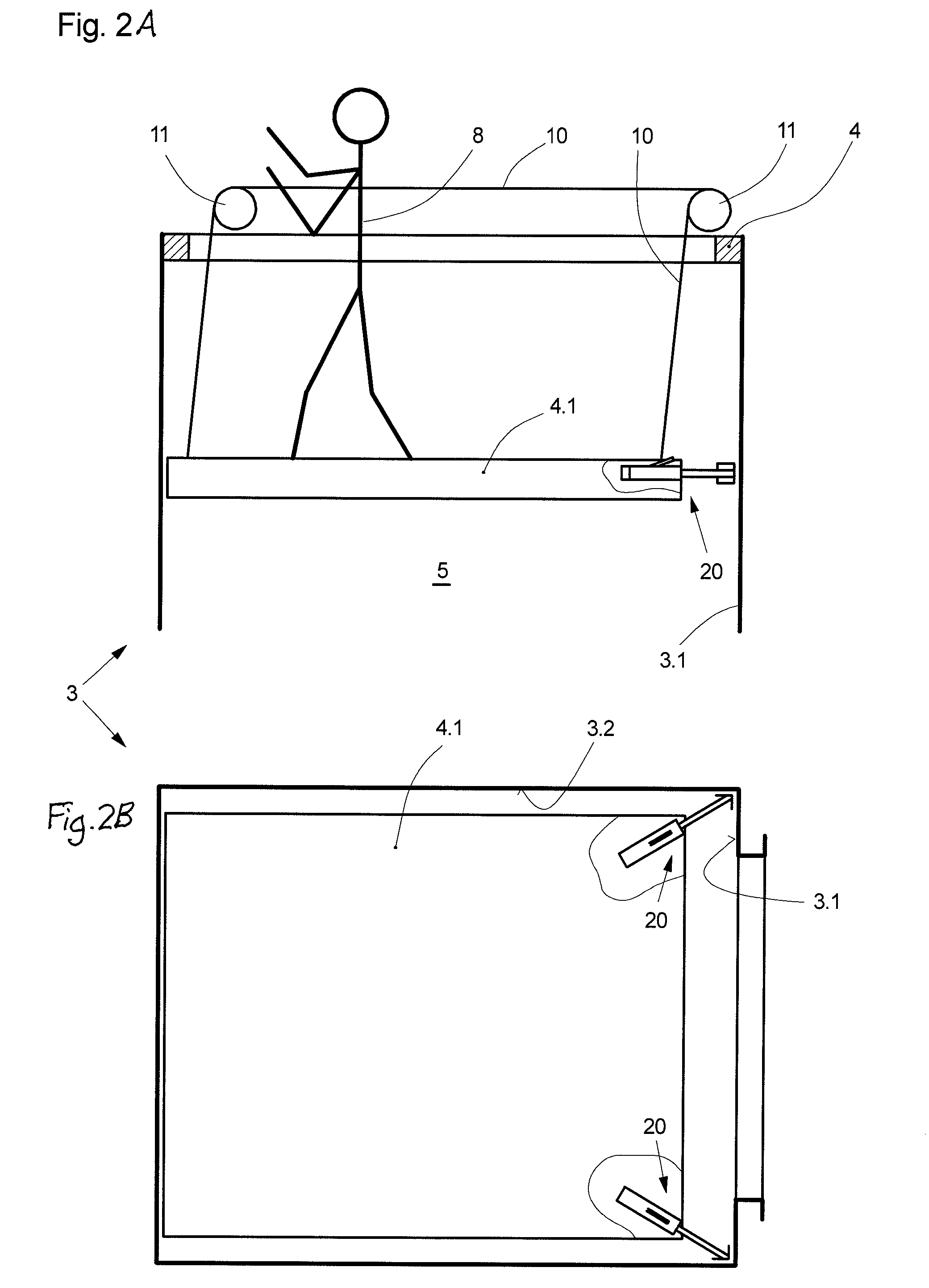
The stabilization device prevents damage to the elevator car and provides a stable platform for service engineers, reducing the risk of accidents and maintaining the structural integrity of the interior space during maintenance operations.

Problems solved by technology

These movements of the car roof in the interior space of the elevator car can lead to damage of the elevator car.

Method used


Image

  • Elevator car with lowerable roof
  • Elevator car with lowerable roof
  • Elevator car with lowerable roof

Examples


Embodiment Construction

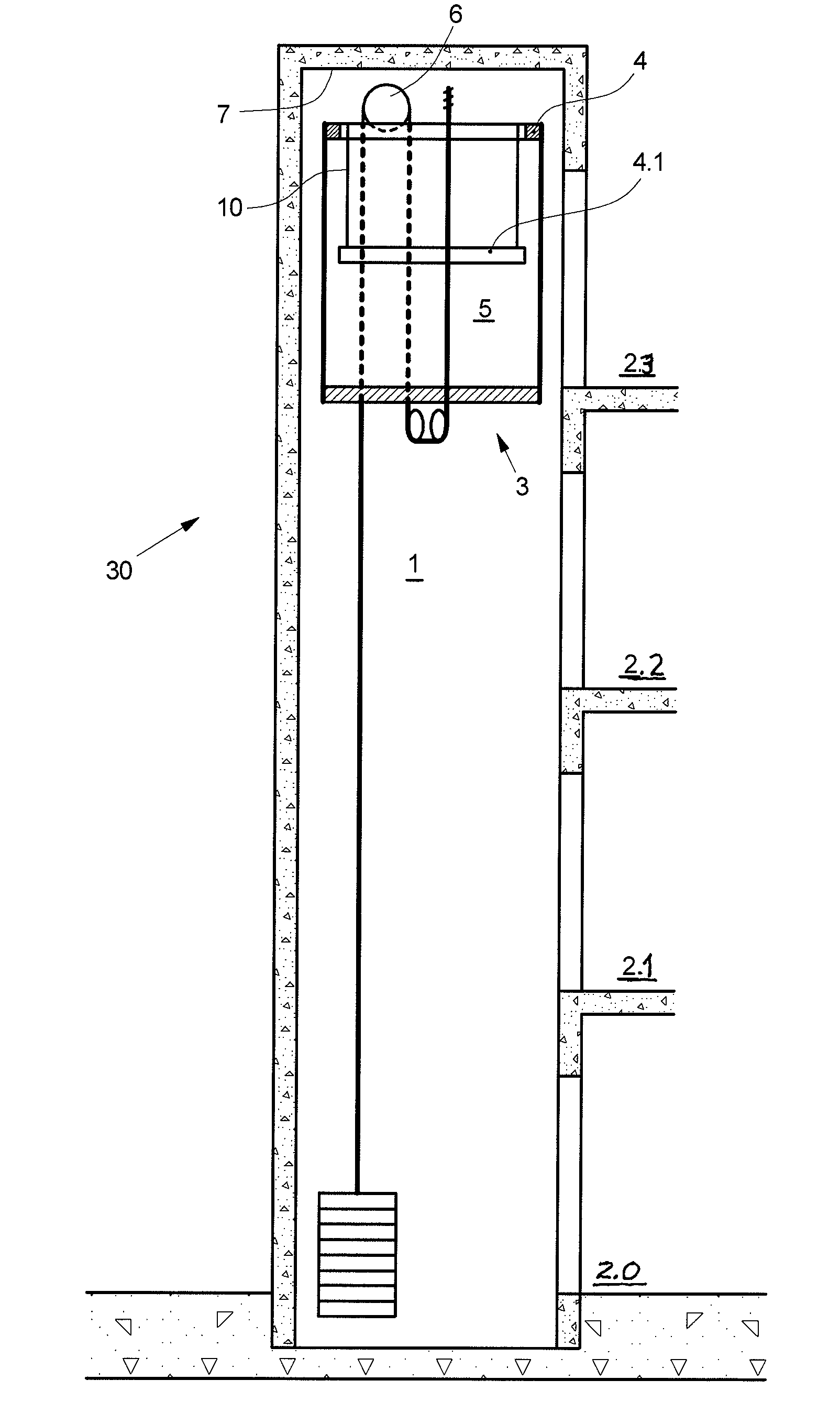
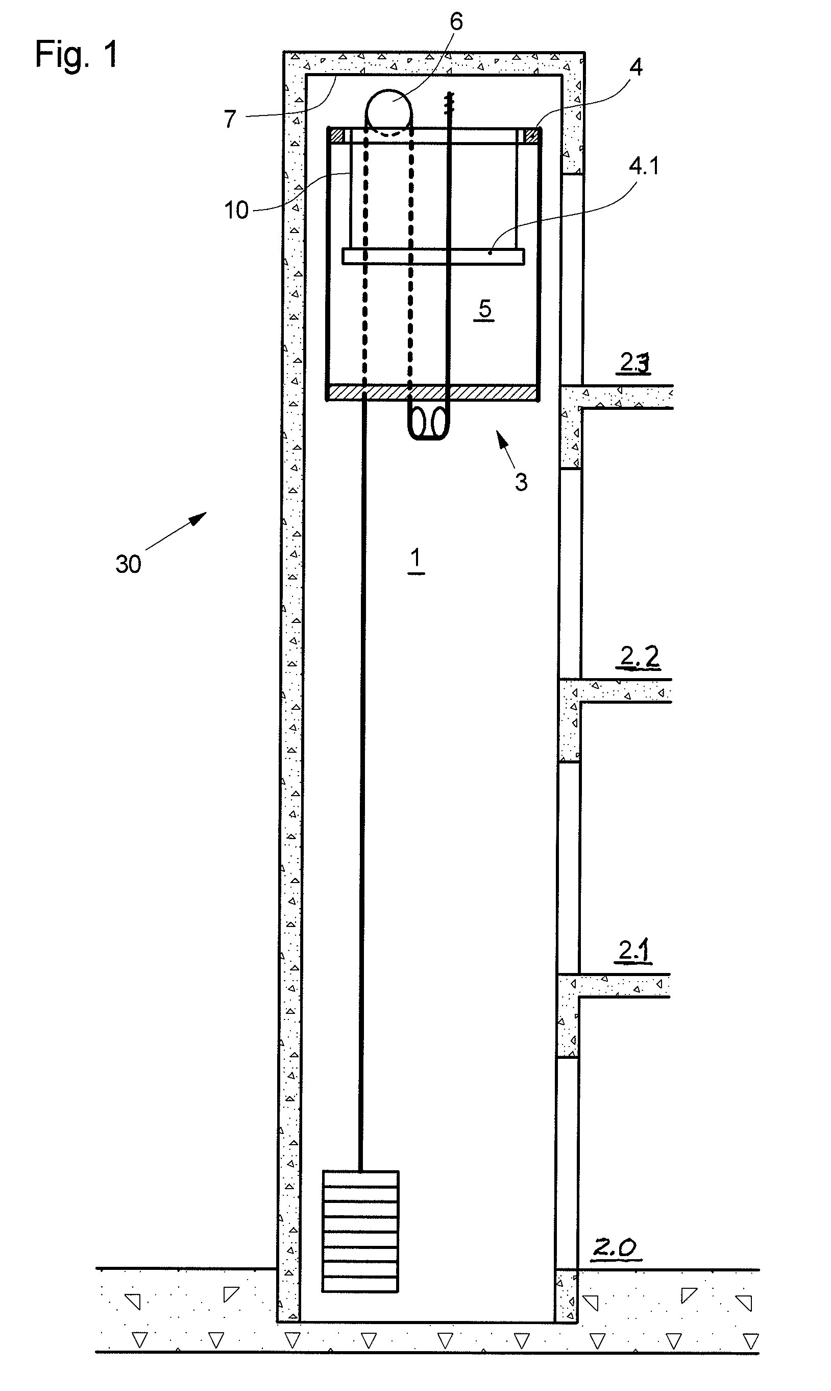
[0022]FIG. 1 shows an elevator installation 30 which is arranged in or at any building and comprises an elevator shaft 1 with an elevator car 3. This can be any elevator installation 30 without a machine room, in which the elevator car 3 driven by a drive system 6 transports passengers or goods in the elevator shaft 1 between floors 2.0, 2.1, 2.2, 2.3 of the building. The elevator shaft 1 is usually separated from the floors by doors (not shown).

[0023]As the elevator shaft 1 without a machine room there is denoted an elevator shaft which does not have available a typical space, which is present additionally to the elevator shaft, for the drive motor. The drive and / or the control of the elevator is or are usually accommodated in this so-termed machine room. Through optimization of the size and output of elevator drive systems the space requirement of the corresponding systems has been continuously reduced. It would be possible through changes in elevator regulations to construct elev...


PUM


Abstract

An elevator car has a lowerable car roof portion serving in the lowered state as a maintenance platform. The lowerable car roof portion is stabilized in the lowered position against movements in a horizontal plane by at least one mechanical device engaging the car roof portion and inner walls of the car.

Description

BACKGROUND OF THE INVENTION[0001]The present invention relates to an elevator car with a car roof lowerable into the interior space of the elevator car.[0002]In conventional elevator installations there is usually present above the end, which is determined by the uppermost position of the elevator car, of an elevator shaft an additional annex in which the drive system and other components of the elevator are accommodated. Reduced dimensions of the drive systems and changed elevator constructional regulations currently make it possible to offer so-termed machine-room-free elevators in which the elevator components are mounted in the elevator shaft and no additional annex (machine room) is present. Checks and maintenance operations of the elevator components mounted in the elevator shaft are usually carried out in such an elevator installation by a service engineer standing on the roof of the elevator car. The elevator car together with the service engineer is for this purpose moved b...

Claims


Application Information

Patent Timeline
Patent Type & Authority Patents(United States)
IPC IPC(8): B66B13/28B66B1/34
CPCB66B11/0246B66B11/02B66B5/00
Inventor SITTLER, DENIS
Owner INVENTIO AG
Learn More