Ball identifying device

a technology of identifying device and ball, which is applied in the field of identifying spherical objects, can solve the problem that certain code-reading technologies are incapable of discriminating between two balls

Inactive Publication Date: 2008-03-04
TOPGOLF SYST
View PDF7 Cites 87 Cited by
  • Summary
  • Abstract
  • Description
  • Claims
  • Application Information

AI Technical Summary

Benefits of technology

[0015]According to a second aspect of the present invention, there is provided a method of ensuring that the code of a coded spherical object can be read by a sensing member comprising moving the object along a helical track and at the same time through or past the sensing member.

Problems solved by technology

This can cause jamming.
In addition, certain code-reading technologies are incapable of discriminating between two balls if they are too close.

Method used


Image

  • Ball identifying device
  • Ball identifying device
  • Ball identifying device

Examples


second embodiment

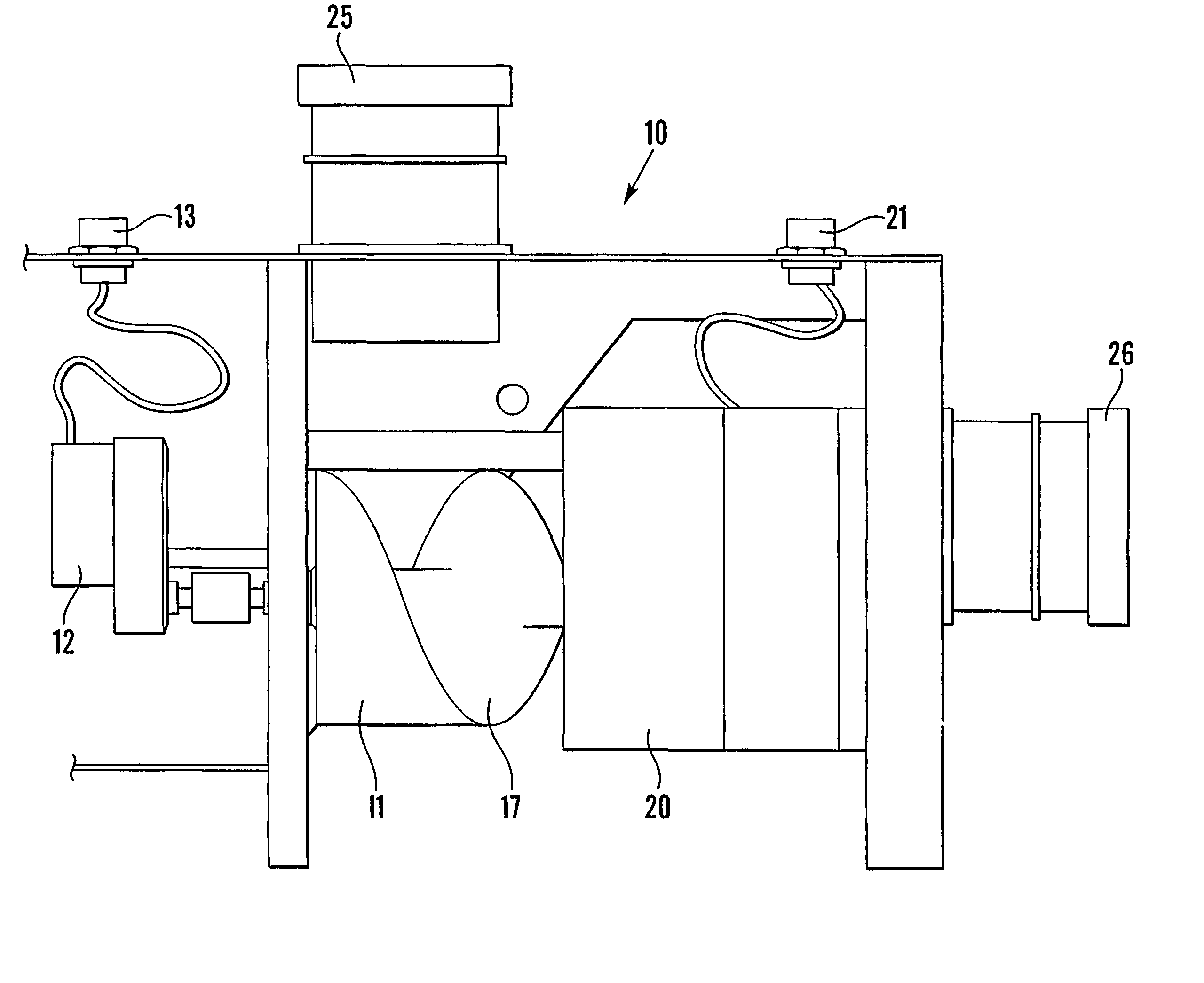
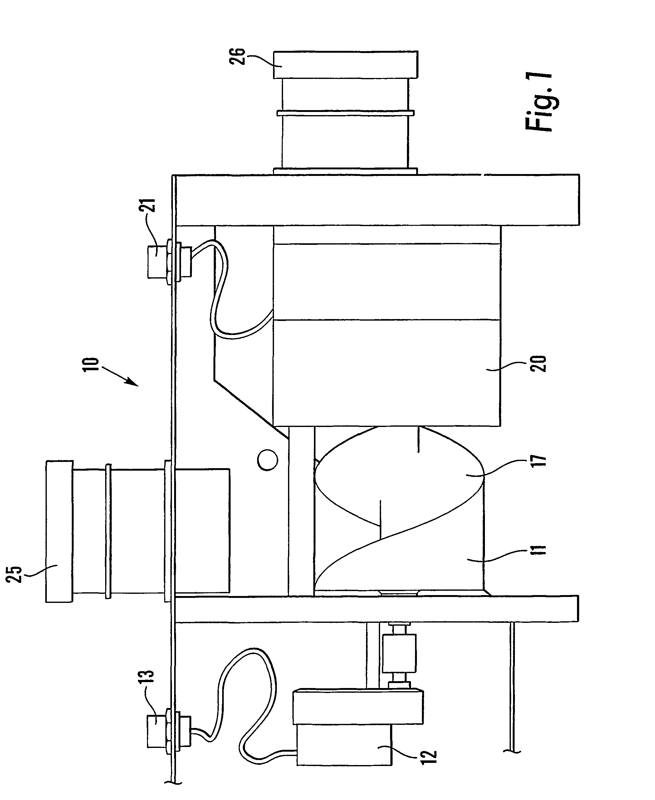
[0031]FIG. 3 shows the present invention in which a ball identification device 50 has a helical screw 11 with a vertical axis, the balls travelling along groove 17 under the effect of gravity. The spacing between the screw 11 and the inner face of housing 20 is such that balls can travel to outlet 26 without jamming. This embodiment has the advantage of not requiring a power supply 13 since it has no moving parts.

third embodiment

[0032]FIG. 4 shows the present invention in which a ball identification device 60 comprises a cylindrical core 62 with a helical track 63 located radially outwardly thereof in the manner of a helter-skelter. Again there are no moving parts, and a ball 61 travels freely along the track to outlet 66.

[0033]The antenna can be arranged inside core 62 if desired.

[0034]The second and third embodiments are suitable for coding technologies which can discriminate between immediately-adjacent golf balls. However, if desired a ball separating device may be provided upstream to maintain a desired minimum distance between successive balls.

fourth embodiment

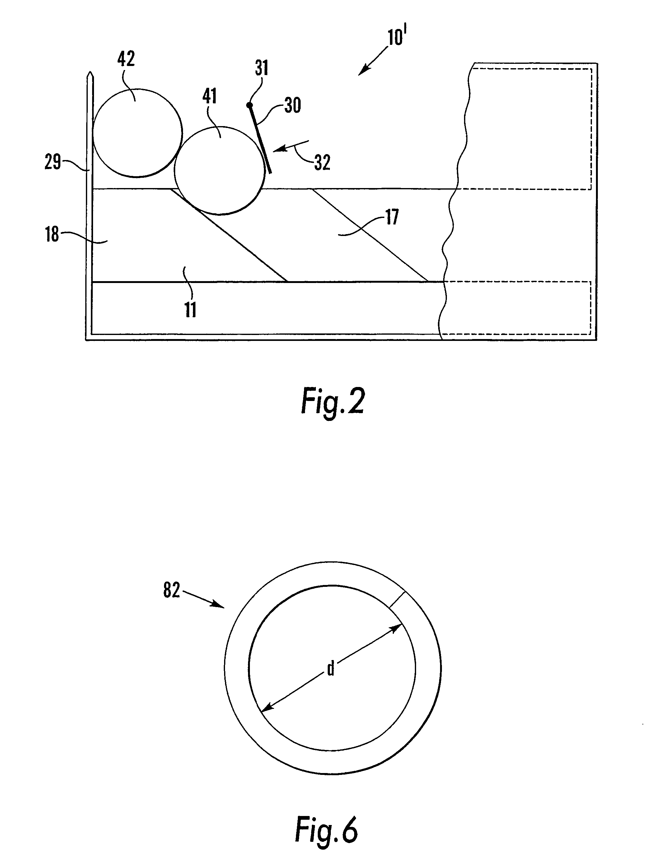
[0035]Referring now to FIGS. 5 and 6, the ball identification device 80 comprises a generally cylindrical housing 81 with a helical track 82 located on its inner surface. The housing 81 may be constituted by a standard pipe fitting and its internal diameter is slightly larger than that of a golf ball. The internal diameter “d” of the track 82 as seen in FIG. 6 is 3 mm less than that of a golf ball. Accordingly a golf ball passing vertically through the housing 81 is constrained to rotate to follow the track 82. The pitch of track 82 is substantially 38 mm and it extends for substantially one and half turns. Track 82 may be formed integrally with housing 81, e.g. by moulding, or may be a separate component attached to housing 81.

[0036]Surrounding the exit of the housing 81 at the bottom is an antenna coil 85 for reading the code on a passing ball.

[0037]An advantage of the fourth embodiment is that it is generally compact and occupies less space than the third embodiment. In addition,...


PUM


Abstract

A device (80) for reading a coded golf ball (40) comprises a helical track (82) on the inside or outside of a cylindrical housing (81), the track serving to change the orientation of the ball relative to an antenna coil (85) to ensure that the code is read. The track may be arranged horizontally and rotated by a motor; a flap (30) may be provided to avoid balls following each other too closely onto the helical track. Alternatively the track may be arranged vertically and the balls may fall under gravity.

Description

BACKGROUND OF THE INVENTION[0001]1. Field of the Invention[0002]The present invention relates to the identification of spherical objects and in particular to the identification of coded golf balls in a golf game or a golf driving range as disclosed in WO 99 / 48046.[0003]2. Description of the Related Art[0004]A problem in detecting a spherical object (such as a golf ball) when it is stationary or moving in a straight line, is that the orientation of a transponder within the object may be such that it is not detected by a sensing antenna. Moreover, in automated golf driving ranges as disclosed in WO 99 / 48046, stopping a ball for code-reading purposes introduces unnecessary delay.BRIEF SUMMARY OF THE INVENTION[0005]Accordingly the present invention seeks to provide an arrangement for reading a coded object while it is moving.[0006]When moving golf balls around an automated golf driving range, they can accumulate upstream of reading devices. This can cause jamming. In addition, certain c...

Claims


Application Information

Patent Timeline
Patent Type & Authority Patents(United States)
IPC IPC(8): G06K7/00A63B69/36A63B43/00G06K7/08G06K13/06G06K13/063G06K17/00G06K19/07
CPCA63B43/00G06K7/08A63B2225/15A63B2225/54
Inventor THIRKETTLE, JOHN S.JOLLIFFE, DAVID V.
Owner TOPGOLF SYST
Why Eureka
Try Eureka