Flighting and tool holder

a technology of scarifier and flight block, which is applied in the direction of cutting machines, slitting machines, manufacturing tools, etc., can solve the problems of cutting bits no longer being retained, machine stopping often for considerable lengths of time, and considerable expense for road-mining machine operators, etc., and achieve the effect of prolonging the life of the flight block

Inactive Publication Date: 2008-03-04
LATHAM WINCHESTER E
View PDF21 Cites 34 Cited by
  • Summary
  • Abstract
  • Description
  • Claims
  • Application Information

AI Technical Summary

Benefits of technology

[0018]In yet another aspect, the tool holder extends outward from the slot beyond the first side wall of the flight block a distance sufficient to protect at least a part of the flight block from abrasion and extend the life of the flight block.

Problems solved by technology

The forces occasionally become large enough to shear the securing bolts, causing the machine to be stopped often for considerable lengths of time.
This is a time-consuming repair job which results in considerable expense to the road-mining machine operator.
Particularly in the presence of abrasive dust from the roadway mining operation, the vibration and movement of the cutting bits act to enlarge the recesses to such an extent that the cutting bit is no longer retained.
Again, this repair job is difficult to do in the field and still achieve accurate alignment of the support block on the flighting section.
Misalignment of the support block results in undesirable lateral forces on a new cutting bit which in turn results in very fast wear and ultimate failure of the replaced parts.
Therefore, standard rectangular or square tool holders cannot be used.

Method used


Image

  • Flighting and tool holder
  • Flighting and tool holder
  • Flighting and tool holder

Examples


Embodiment Construction

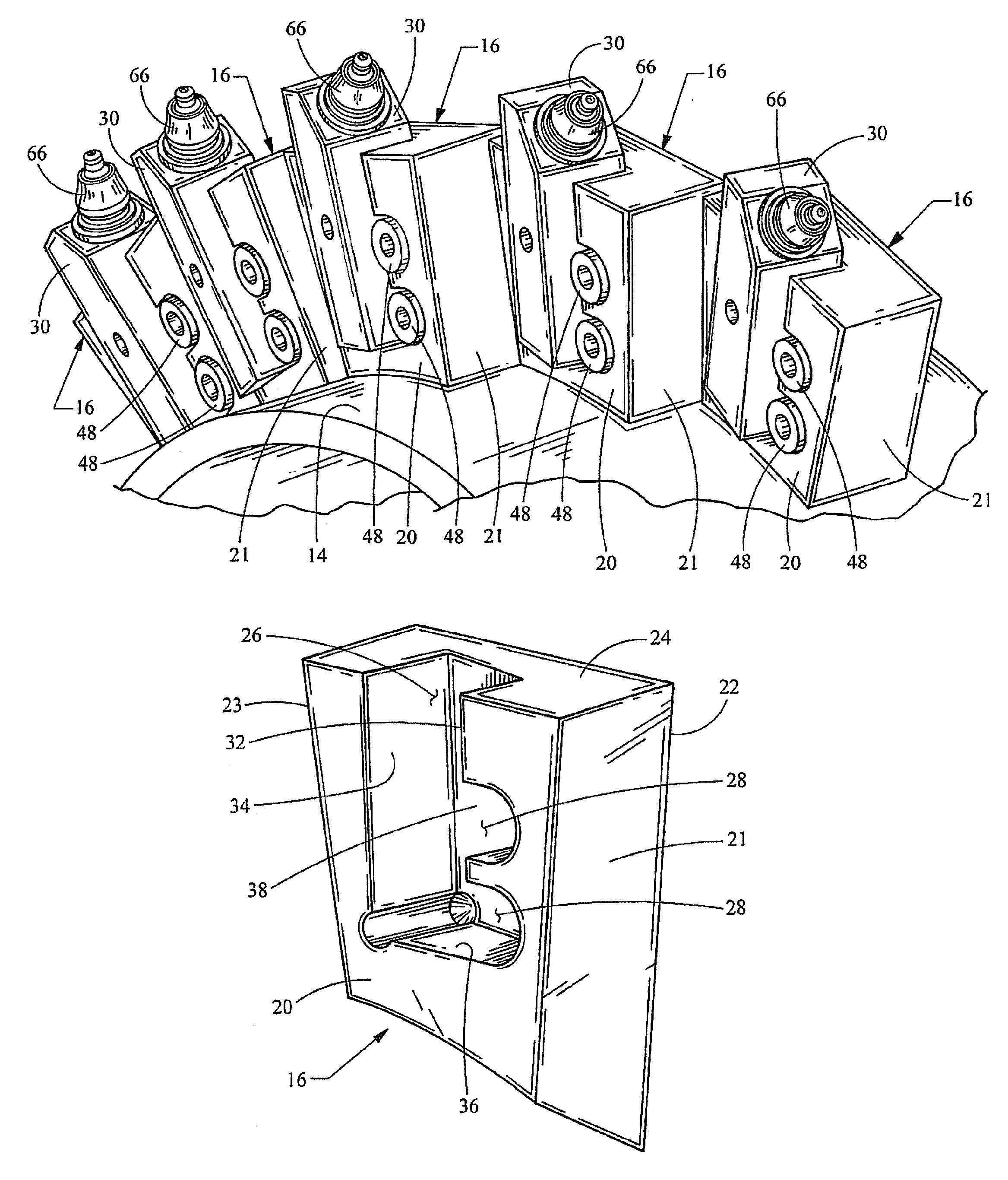
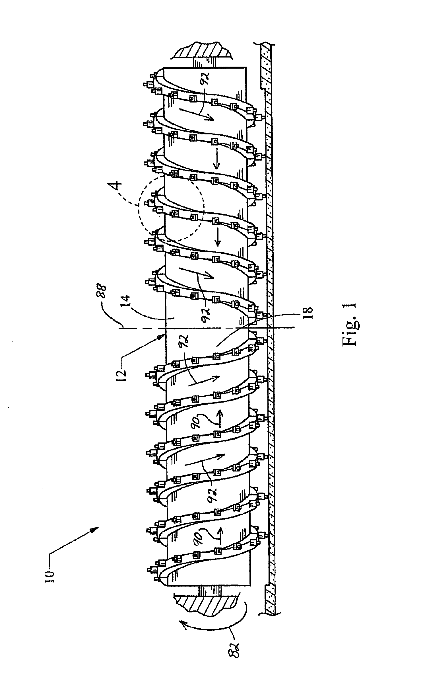
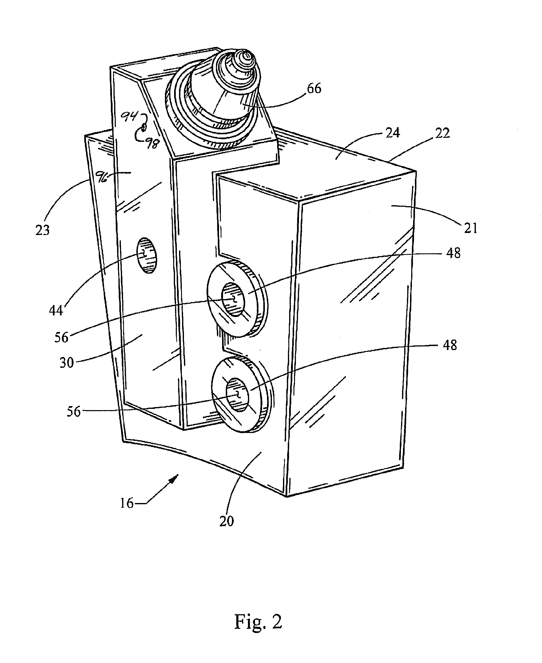
[0037]Referring to FIG. 1, a cutting drum for a scarifying milling machine having features in accordance with the accompanying claims is shown generally at 10. The cutting drum 10 includes a rotatable drum 12 having a generally cylindrical outer surface 14. A plurality of flight blocks 16 are mounted onto the outer surface 14 of the drum 12. A single flight block 16 is shown in FIG. 2. The flight blocks 16 are positioned on the drum 12 relative to one another such that the flight blocks 16 define a helical flight 18 extending around the outer surface 14 of the drum 12, as shown in FIGS. 1, 3, and 4.

[0038]Referring to FIGS. 5, 6, and 7, each flight block 16 has a first side wall 20, a front surface 21, a second side wall 22, a rear surface 23, and a top surface 24. The first and second side walls 20, 22 are generally parallel to one another and generally perpendicular to the drum 12. The top surfaces 24 of the flight blocks 16 define an outer periphery of the flight 18.

[0039]Referrin...


PUM

PropertyMeasurementUnit
angleaaaaaaaaaa
angleaaaaaaaaaa
angleaaaaaaaaaa

Abstract

A cutting drum for a scarifying milling machine includes a rotatable drum having a generally cylindrical outer surface, and a plurality of flight blocks mounted onto the outer surface of the drum, defining a helical flight extending therearound. Each of the flight blocks includes a slot and at least one pocket formed therein. Each slot is generally rectangular and adapted to receive a tool holder. Each flight block includes a tool holder, having a generally rectangular body, removably mounted within the slot. A retainer is positioned within each pocket. Each retainer includes a planar tapered surface that is parallel to and engages one side of the rectangular body of the tool holder within the slot of the flight block to secure the tool holder therein.

Description

BACKGROUND[0001]1. Field of the Invention[0002]The invention generally relates to rotary driven cylindrical cutters and scarifiers for use in earth-working, mining, or other in situ disintegration of hard materials. The invention is particularly directed to such rotary driven cylindrical cutters and scarifiers as incorporate means for feeding or excavating the material cut or mined away from its initial location generally to a second material carrier.[0003]2. Background of the Invention[0004]In general, roadway mining or planing equipment includes a rotary driven cylindrical comminuting drum which acts to scarify and to mine the top portion of the asphaltic road surface in situ. The rotary driven drum includes flighting on the drum which acts to collect and move the mined material toward the center of the drum where it can be removed. Often the mined material is then remixed with additional bituminous material and thereafter re-deposited as a newly formed smooth asphaltic surface.[0...

Claims


Application Information

Patent Timeline
Patent Type & Authority Patents(United States)
IPC IPC(8): E21C35/18
CPCB28D1/188E21C25/10E21C35/1936E21C2035/191E21C35/191
Inventor LATHAM, WINCHESTER E.
Owner LATHAM WINCHESTER E
Why Eureka
Try Eureka