Loopback optical receiving-transmitting module and its testing device and method

A technology of optical transceiver module and optical module, which is applied in the direction of electromagnetic transceiver, transmission monitoring/testing/fault measurement system, electromagnetic wave transmission system, etc., can solve the problems of excessive aging of XFP optical module, reduce failure rate, and shorten service life, and achieve Avoid the increase of failure rate, avoid the shortening of life, and reduce the cost of equipment

Inactive Publication Date: 2008-01-23
ZTE CORP
View PDF1 Cites 18 Cited by
  • Summary
  • Abstract
  • Description
  • Claims
  • Application Information

AI Technical Summary

Problems solved by technology

[0005] In order to solve the problems that the existing optical module testing method causes the XFP optical module to be over-aged, its life is shortened and its failure rate is reduced, the present invention provides a self-loop optical transceiver module and its testing device and method

Method used


Image

  • Loopback optical receiving-transmitting module and its testing device and method

Examples


Embodiment Construction

[0021] Various preferred embodiments of the present invention will be described in detail below.

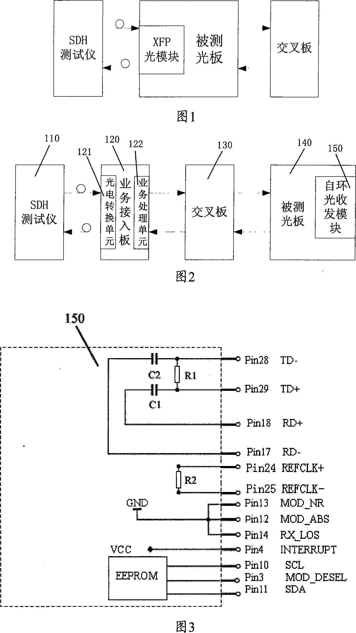
[0022] As shown in Figure 3, the self-loop optical transceiver module 150 of the present invention includes a double LC optical interface that meets the requirements of the XFP MSA multi-source agreement and an optical module electrical interface with 30 pins, and the differential signal input of the optical module electrical interface Terminals Pin17 (RD-) and Pin18 (RD+) are connected to the differential signal output terminals Pin28 (TD-) and Pin29 (TD+) of the electrical interface of the optical module through the serially connected capacitors C1 and C2, respectively. A resistor R1 is connected between the two differential signal output terminals Pin28 (TD-) and Pin29 (TD+) of the optical module electrical interface. The resistors across the two differential signal input terminals Pin17 (RD-) and Pin18 (RD+) are differential signal impedance matching resistors, and the capaci...


PUM


Abstract

The present invention discloses self-loop optical receiving/transmitting module, a test device and a method. Wherein, the module comprises an electrical interface for the optical receiving/ transmitting module in compliance with requirements for multi-source stipulations on small-sized packaging and hot plug. A differential signal input terminal of the electrical interface is correspondingly connected with a differential signal output terminal of the electrical interface through a series capacitance. A resistance is connected between two differential signal output terminals of the electrical interface. The self-loop optical receiving/transmitting module disclosed by the present invention can replace an actual XFP optical module of normal functions, realizes internal loop of communications in the optical module and is mounted in an optical interface board of equipment and suitable for extensive application to equipment test and aging, thus reducing optical module aging to some extent and avoiding reduced service life and increased failure rate of the optical module due to aging.

Description

technical field [0001] The present invention relates to the technical field of communication equipment, and in particular to the application technical field of 10Gbit / s small-package hot-pluggable optical module (XFP, 10Gigabit Small Form Factor Pluggable). MSA, Multi-source Agreement) INF8077i version requirements. Background technique [0002] The XFP optical module (10Gbit / s small-package hot-swappable optical module), which has the advantages of small package and hot-swappable, has been widely used in the communication field. [0003] In the production and testing process of communication equipment, the components of the equipment (various boards) have to undergo various tests to achieve quality control after the production is completed, one of which is the long-term high-temperature aging test. Among these boards are single boards commonly called optical interface boards. Optical modules play an indispensable and important role in optical-electrical / electrical-optical ...

Claims


Application Information

Patent Timeline
Patent Type & Authority Applications(China)
IPC IPC(8): H04B10/02H04B10/08H04B10/07H04B10/40
Inventor 李璞
Owner ZTE CORP
Why Eureka
Try Eureka