Quick-connect fastener assembly

a fastener and assembly technology, applied in the field of fasteners, can solve the problems of long task, affecting the quality of fasteners, and generally replacing or supplanting bolts, and other types of connectors are usually not as satisfactory

Inactive Publication Date: 2008-03-04
ELLIS GARY L +1
View PDF13 Cites 21 Cited by
  • Summary
  • Abstract
  • Description
  • Claims
  • Application Information

AI Technical Summary

Benefits of technology

[0008]Using the embodying the present invention will permit a nut to be quickly located on a bolt, even a very long bolt, without threadably engaging that bolt and then to be quickly, yet securely, threadably engaged with that bolt once the nut reaches the desired location on the bolt. The washer will be easily and quickly positioned on the bolt, and will then securely maintain the nut in threaded engagement with the bolt when desired. Thus, a nut can be placed on a long bolt and secured thereto even if the bolt is very long and the nut is to be located in a difficult-to-reach location, and will remain secured to the bolt.

Problems solved by technology

Since a nut must be coupled to the stud by threading, it can be a lengthy task to move a nut all the way up a long stud to the desired location.
Various types of quick-connect couplers have been proposed for a number of uses, but none have generally replaced or supplanted bolts and nuts, simply because bolts and nuts are cheap, and can provide strong and secure connections.
Thus, even though an attachment by a bolt and nut is slow when a premium is placed upon a workman's time, other types of connectors are usually not as satisfactory.
While these prior art quick-locking fasteners generally work well, they often require a wedging action for the nut to remain in place.
If the fastener assembly is subject to vibration or other shocking action, the wedging action may become loose over time which may tend to loosen the fastener.
Still further, many of the prior art quick-locking fasteners are complicated and hence expensive.
Still further, some of the prior art quick-connect fasteners require one portion of the fastener to abut against another structure, such as the workpiece or the like.
This may not always be convenient.

Method used


Image

  • Quick-connect fastener assembly
  • Quick-connect fastener assembly
  • Quick-connect fastener assembly

Examples


Embodiment Construction

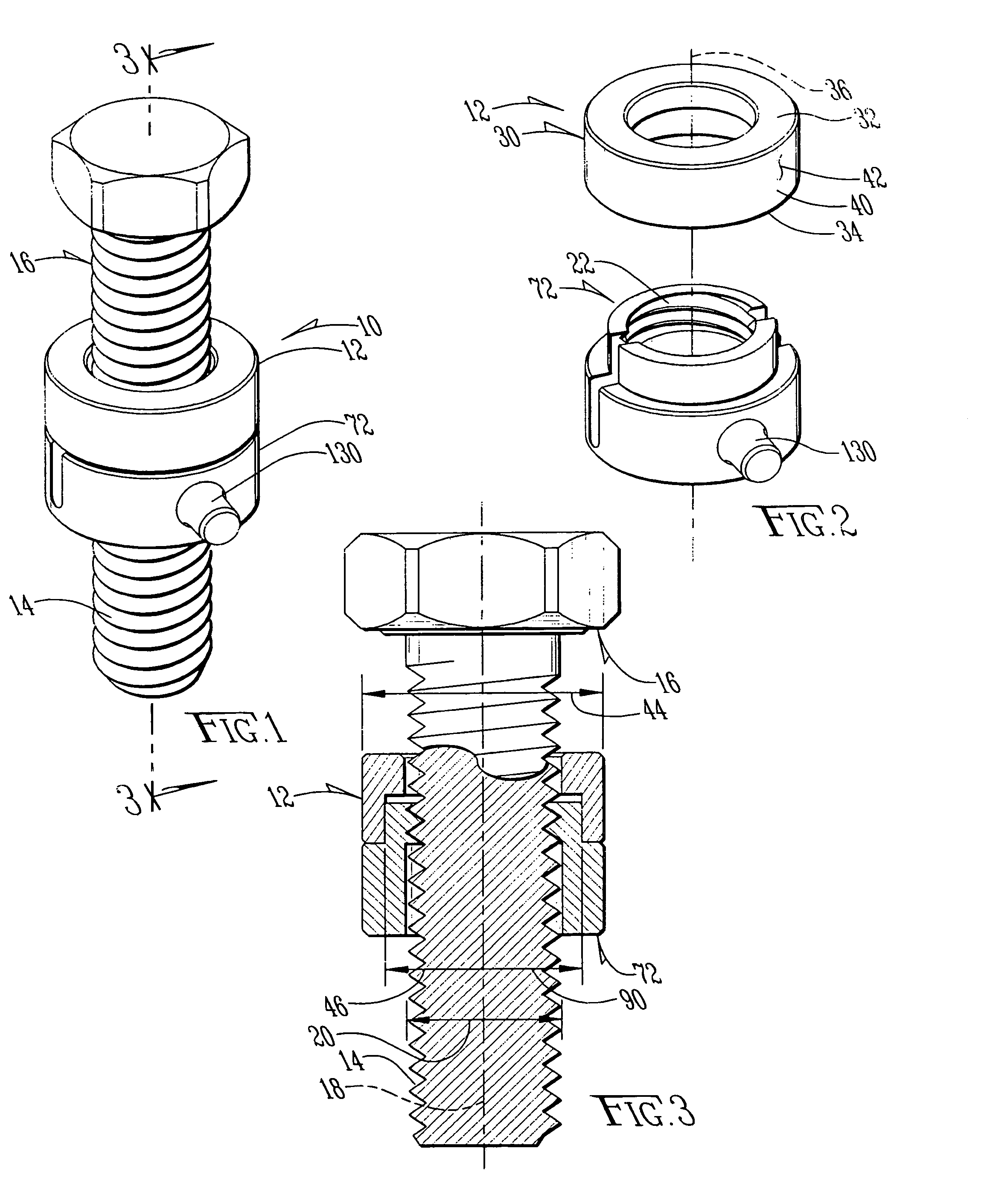
[0018]Referring to the figures, it can be understood that the present invention is embodied in a quick-connect fastener assembly 10 which achieves the objectives of the present invention.

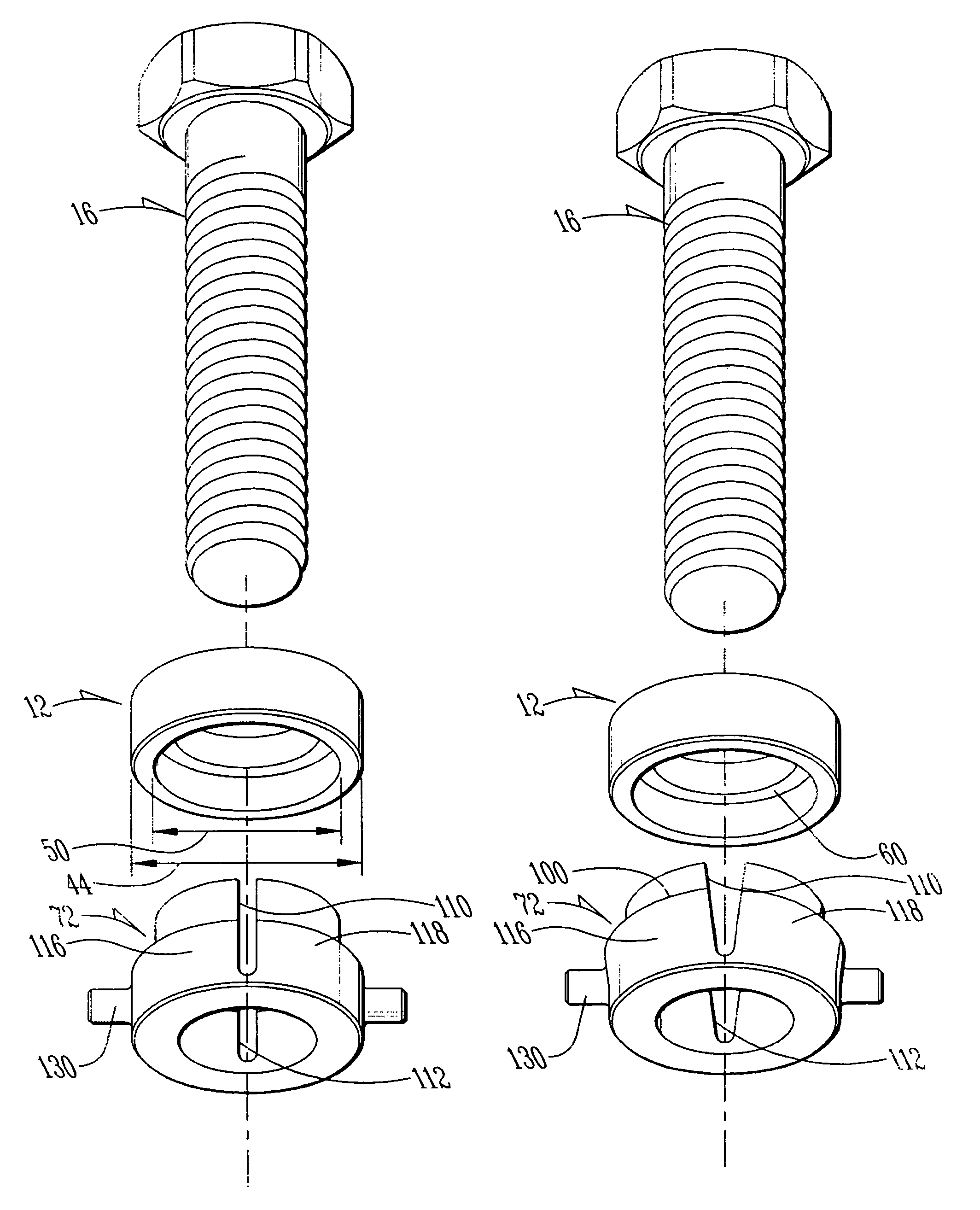
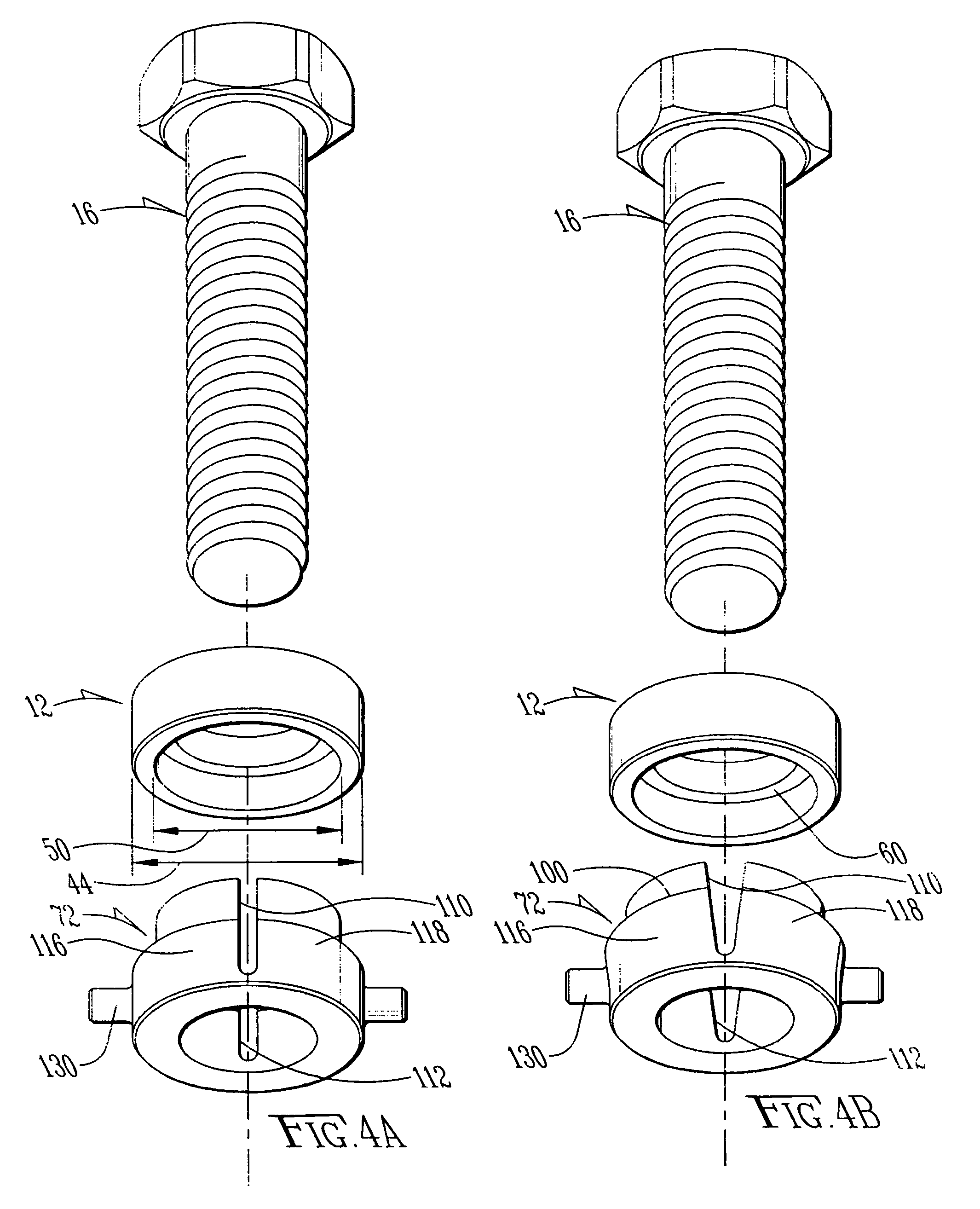
[0019]Assembly 10 comprises a washer element 12 that fits onto a threaded portion 14 of a long bolt 16 having a longitudinal axis 18 and an outer diameter 20 when in us. Washer element 12 includes an annular body 30 which has a first end 32, a second end 34 and a longitudinal axis 36 which extends between first end 32 and second end 34 and which is co-linear with longitudinal axis 18 of bolt 14 when the washer is in place on the bolt as shown in FIG. 2.

[0020]An outer cylindrical wall 40 of washer element 12 connects first and second ends 32 and 34. Wall 40 includes an outer surface 42 having an outer diameter 44 and an inner surface 46. Inner surface 46 of the wall is stepped and includes a first portion 48 which has a first diameter 50 and which extends from first end 32 of the body towards second ...


PUM


Abstract

A fastener assembly includes a washer element and a nut element. The nut element is split and includes a screw thread that threadably engages the thread of a bolt or other such fastener element to lock the nut to the bolt. The nut element is adapted by the split to assume an open configuration which permits the nut to move freely along the bolt without being threadably engaged with the bolt and a closed configuration which threadably engages the screw thread of the nut with the screw thread of the bolt. The washer is sized to move freely over the screw thread of the bolt, but to force the nut into the closed configuration when the washer and the nut are cooperatively engaged. The washer maintains the nut in threaded engagement with the bolt when the washer and the nut are cooperatively engaged on the bolt.

Description

TECHNICAL FIELD OF THE INVENTION[0001]The present invention relates to the general art of fasteners, and to the particular field of quick-connect fasteners.BACKGROUND OF THE INVENTION[0002]Conventional threaded fasteners may comprise a nut and a corresponding threaded portion on e.g a bolt or a threaded stud which can be used to fasten components. Often, the threaded stud is quite long. Since a nut must be coupled to the stud by threading, it can be a lengthy task to move a nut all the way up a long stud to the desired location. This process may be exacerbated if the coupling unit is located in a difficult-to-reach location.[0003]Therefore, there is a need, especially in the construction industry, for couplers and nuts which can quickly and easily interconnect two members and then, perhaps later, tightly secure them together. Various types of quick-connect couplers have been proposed for a number of uses, but none have generally replaced or supplanted bolts and nuts, simply because ...

Claims


Application Information

Patent Timeline
Patent Type & Authority Patents(United States)
IPC IPC(8): F16B39/01
CPCF16B37/0828F16B43/00
Inventor ELLIS, GARY L.MCGEE, KAY
Owner ELLIS GARY L
Why Eureka
Try Eureka