This helps you quickly interpret patents by identifying the three key elements:
Problems solved by technology
Method used
Benefits of technology
Benefits of technology
[0014]In view of the foregoing disadvantages inherent in the known types of hybrid systems as applied to heavy-duty, tong haul vehicles now p
Problems solved by technology
While these devices fulfill their respective, particular objectives and requirements, the aforementioned patents do not disclose a new hybrid system for heavy-duty Class 8 long-haul type vehicles.
But there is a lack of hybrid systems designed to reduce fuel consumption for long-haul heavy-duty Class 8 trucks, as well as medium-duty Class 4 t
Method used
Image
Click on the blue label to locate the original text in one second.
Reading with bidirectional positioning of images and text.
Examples
Embodiment Construction
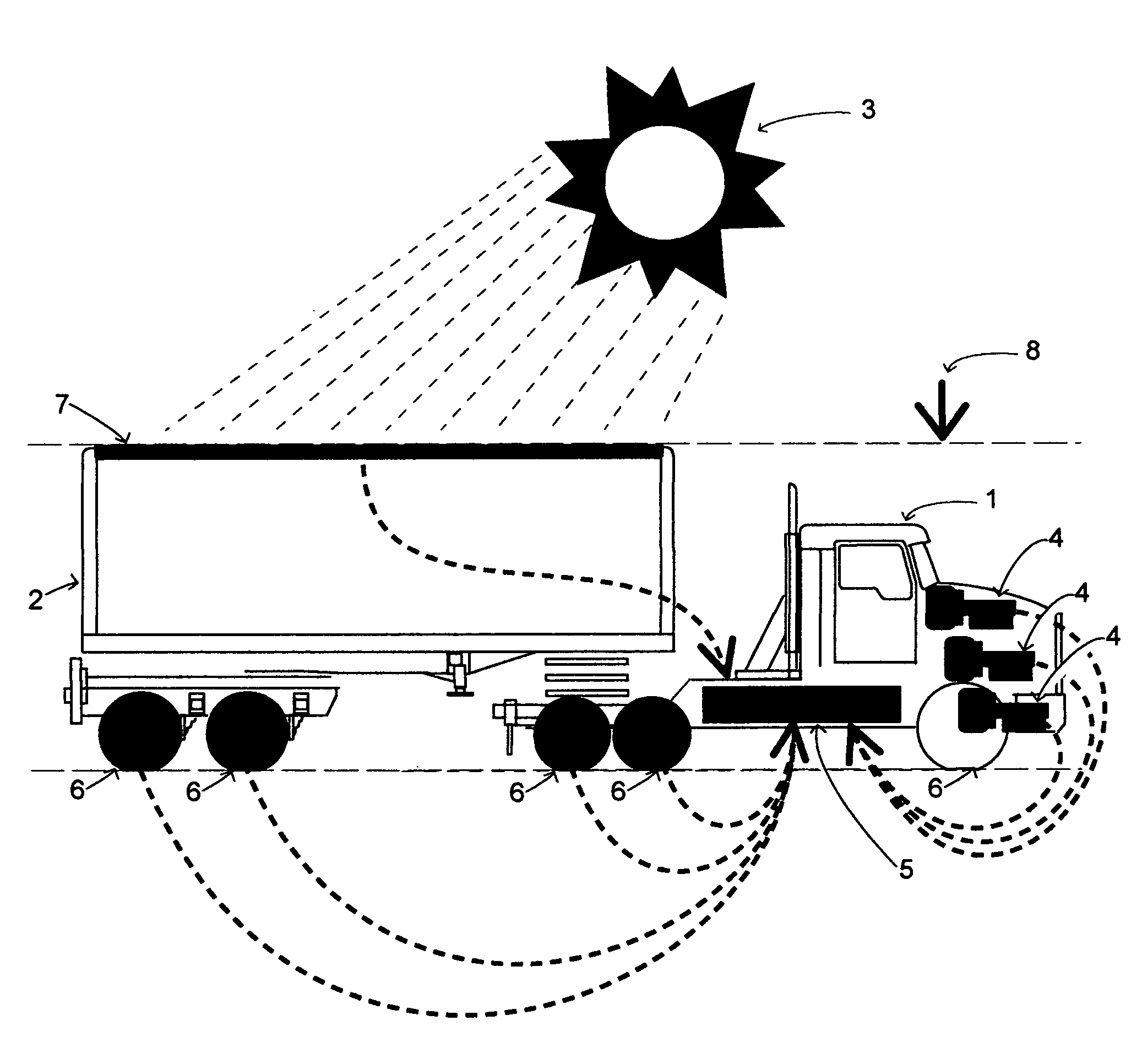
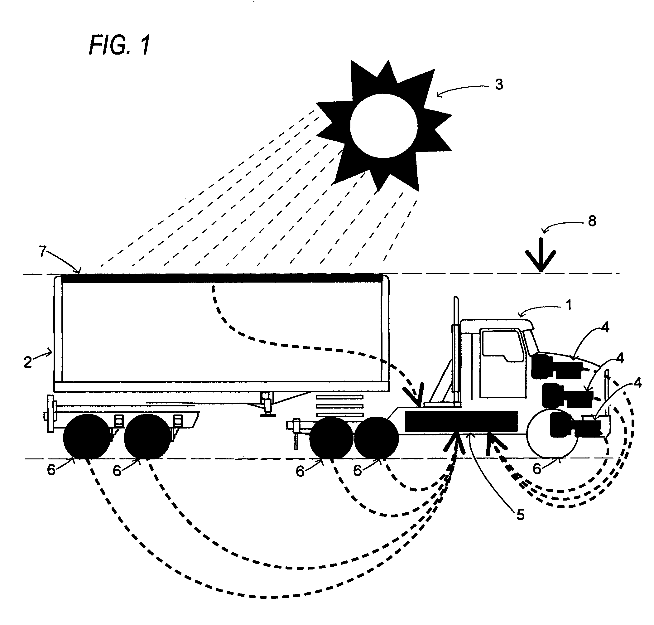
[0084]FIG. 1 is a diagram showing the elements which lower fuel consumption of a vehicle exemplified in one embodiment of the present invention. Shown is a schematic side view of an electric-drive tractor truck 1 and a semi-trailer 2 with the sun 3 above which exemplifies one embodiment of the present invention. Three GenSets 4 and a Battery Module 5 are shown in the tractor truck. Road-Wheel Modules 6 are shown under the tractor truck and the semi-trailer. Atop the semi-trailer is a Photovoltaic Module array 7. And, arrow 8 indicates the roof height of the semi-trailer.
[0085]In operation, the individual GenSets 4 automatically turn on and off to meet the net power demands of the vehicle. While three GenSets are shown in the diagram for simplicity, any number that is suitable for the application can be used. The electrical current is diagrammatically shown in broken lines traveling to the Battery Module 5. In practice, the GenSets charge the Battery Module(s) and also optionally dir...
PUM
Abstract
A hybrid electric system designed to lower fuel consumption in heavy-duty long-haul vehicles, and in medium and light duty vehicles (trucks, buses, vans, SUVs, recreational vehicles, and the like), utilizing a multiplicity of thermal engines, regenerative power road-wheels, solar cells, and frontal area reducing adjustable-height suspension that are utilized singly or in combinations as suits the vehicle's mission.
Description
CROSS-REFERENCE TO RELATED APPLICATIONS[0001]This Hybrid Electric Heavy-Duty Vehicle Drive System patent application is a Continuation-In-Part of my patent application Ser. No. 10 / 712,227, filed Nov. 14, 2003, titled “Amphibious Recreational Vehicle” and now U.S. Pat. No. 6,840,825, and which is a Continuation-In-Part of application Ser. No. 10 / 177,314, filed Jun. 24, 2002, titled “Comprehensive Vehicle Construction And Hybrid Electric Drive System” and now U.S. Pat. No. 6,679,543, and which is a Continuation-In-Part of my patent application Ser. No. 09 / 766,966, filed Jan. 23, 2001, titled “Rooftop Deck Systems For Vehicles”, and now U.S. Pat. No. 6,425,625.[0002]Application Ser. No. 10 / 177,314 is also a Continuation-In-Part of application Ser. No. 10 / 142,403, filed May 10, 2002, titled “Seating, Handrails & Canopy For Rooftop Deck Vehicles” and now abandoned, and which relates to my previous patent application Ser. No. 09 / 491,764, filed Jan. 27, 2000, titled “Streamline Rooftop Dec...
Claims
Application Information
Patent Timeline
Application Date:The date an application was filed.
Publication Date:The date a patent or application was officially published.
First Publication Date:The earliest publication date of a patent with the same application number.
Issue Date:Publication date of the patent grant document.
PCT Entry Date:The Entry date of PCT National Phase.
Estimated Expiry Date:The statutory expiry date of a patent right according to the Patent Law, and it is the longest term of protection that the patent right can achieve without the termination of the patent right due to other reasons(Term extension factor has been taken into account ).
Invalid Date:Actual expiry date is based on effective date or publication date of legal transaction data of invalid patent.

