Method for etching and for forming a contact hole using thereof
a technology of contact hole and etching, which is applied in the direction of basic electric elements, semiconductor/solid-state device manufacturing, electric devices, etc., can solve the problems of increasing manufacturing costs, limiting the horizontal direction of dimension increase, and uneven degree of photo resist pattern tapering after thermal reflow
- Summary
- Abstract
- Description
- Claims
- Application Information
AI Technical Summary
Benefits of technology
Problems solved by technology
Method used
Image
Examples
embodiment 1
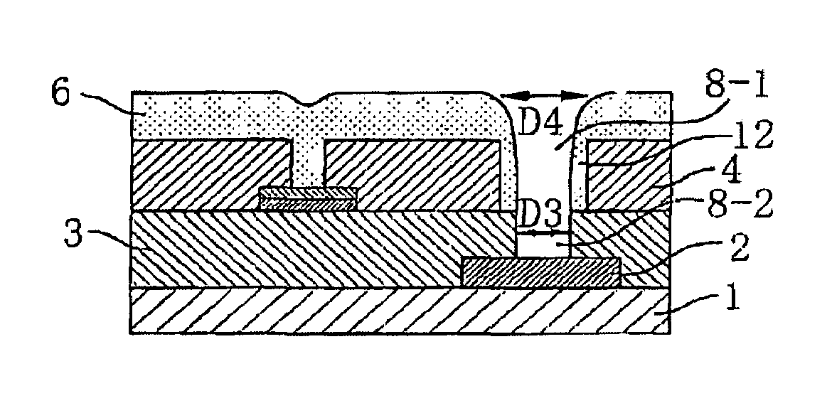
[0201]Embodiment 1 will be explained below. The embodiment 1 corresponds to the typical example that conducts the first to the third aspects of the present invention. FIGS. 4A to 4E illustrate longitudinal cross sectional views showing a series of processes forming a plurality of holes with different depth through one time process of the lithography with regard to the embodiment 1 of the present invention.
[0202]As illustrated in FIG. 4A, a first conductive constituent part 2 is selectively formed on a substrate 1. The substrate 1 can be formed with an insulating substrate. The insulating substrate may be, for example, a transparent substrate such as glasses for the use of the liquid crystal display device, and insulating films such as amorphous silicon, silicon dioxide films, silicon nitride films, silicon dioxide films and silicon nitride films for the use of semiconductor integrated circuits. In addition the first conductive constituent part 2 can be formed with a conductive film....
embodiment 2
[0224]Embodiment 2 will be explained below. The embodiment 2 corresponds to the typical example that conducts the second, the fourth and the fifth aspects of the present invention. FIGS. 5A to 5E illustrate longitudinal cross sectional views showing a series of processes forming a plurality of holes with different depth through one time process of the lithography with regard to the embodiment 2 of the present invention.
[0225]As illustrated in. FIG. 5A, a first conductive constituent part 52 is selectively formed on a substrate 51. The substrate 51 can be formed with an insulating substrate. The insulating substrate may be, for example, a transparent substrate such as glasses for the use of the liquid crystal display device, and insulating films such as amorphous silicon, silicon dioxide films, silicon nitride films, silicon dioxide films and silicon nitride films for the use of semiconductor integrated circuits. In addition the first conductive constituent part 52 can be formed with...
embodiment 3
[0248]Embodiment 3 will be explained below. The embodiment 3 corresponds to the typical example that conducts the second, the fourth and the sixth aspects of the present invention. FIGS. 6A to 6F illustrate longitudinal cross sectional views showing a series of processes forming a plurality of holes with different depth through one time process of the lithography with regard to the embodiment 3 of the present invention.
[0249]As illustrated in FIG. 6A, a first conductive constituent part 72 is selectively formed on a substrate 71. The substrate 71 can be formed with an insulating substrate. The insulating substrate may be, for example, a transparent substrate such as glasses for the use of the liquid crystal display device, and insulating films such as amorphous silicon, silicon dioxide films, silicon nitride films, silicon dioxide films and silicon nitride films for the use of semiconductor integrated circuits. In addition the first conductive constituent part 72 can be formed with ...
PUM
 Abstract
Description
Claims
Application Information
 - R&D
- Intellectual Property
- Life Sciences
- Materials
- Tech Scout
- Unparalleled Data Quality
- Higher Quality Content
- 60% Fewer Hallucinations
Browse by: Latest US Patents, China's latest patents, Technical Efficacy Thesaurus, Application Domain, Technology Topic, Popular Technical Reports.
© 2025 PatSnap. All rights reserved.Legal|Privacy policy|Modern Slavery Act Transparency Statement|Sitemap|About US| Contact US: help@patsnap.com


