
Impulse tolerant valve assembly

a valve assembly and impulse technology, applied in the direction of valve housings, valve operating means/releasing devices, functional valve types, etc., can solve the problems of narrowing of the corresponding vibration spectrum, achieve effective reduction of ringing, facilitate tuning the damper, and prevent bottoming

Active Publication Date: 2013-10-08
GILSTAD DENNIS W +1
View PDF19 Cites 2 Cited by
  • Summary
  • Abstract
  • Description
  • Claims
  • Application Information

AI Technical Summary

Benefits of technology

This patent describes a valve assembly that is designed to reduce the vibration and noise caused by valve closing energy impulses. The valve contains a special spring-mass dampener that can be adjusted to resonate with multiple frequencies. This dampener is immersed in a liquid that helps to tune it and prevent the valve from vibrating too much when it is closing. As a result, the valve reduces the amount of vibration energy that is transmitted to the pump housing through the valve seat.

Problems solved by technology

And the increased impulse duration results in narrowing of the corresponding induced vibration spectrum.

Method used


Image

  • Impulse tolerant valve assembly
  • Impulse tolerant valve assembly
  • Impulse tolerant valve assembly

Examples


Embodiment Construction

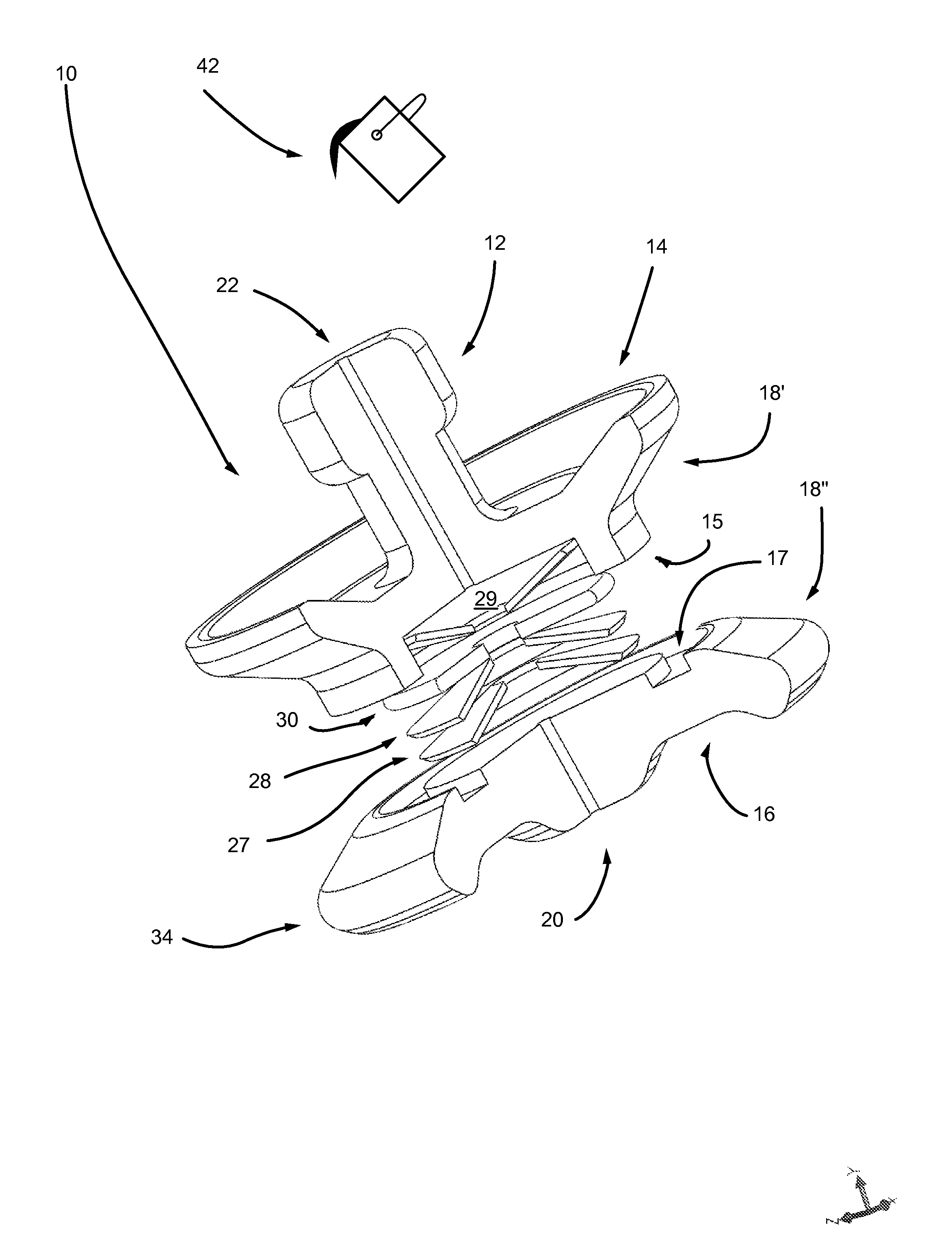
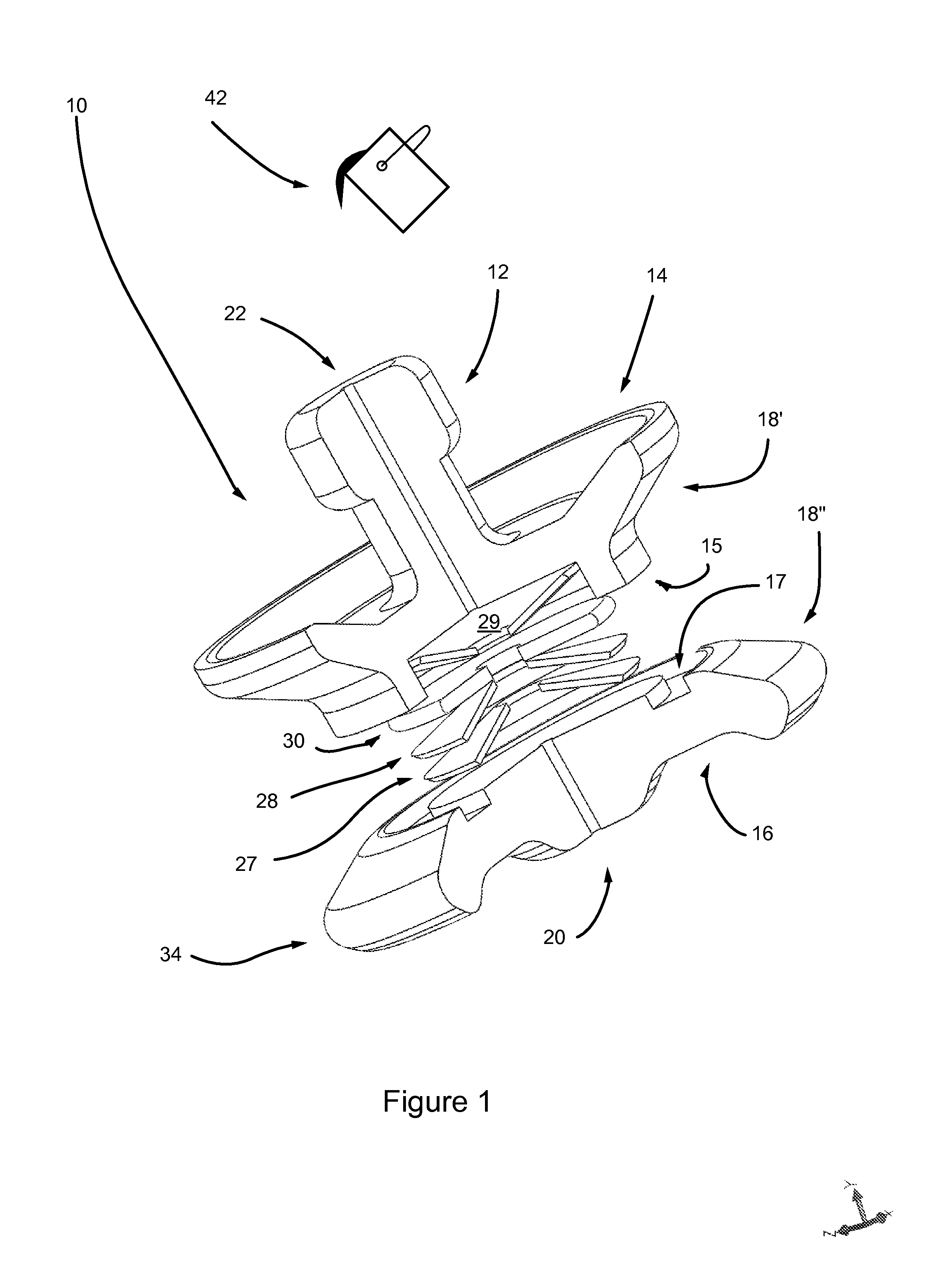
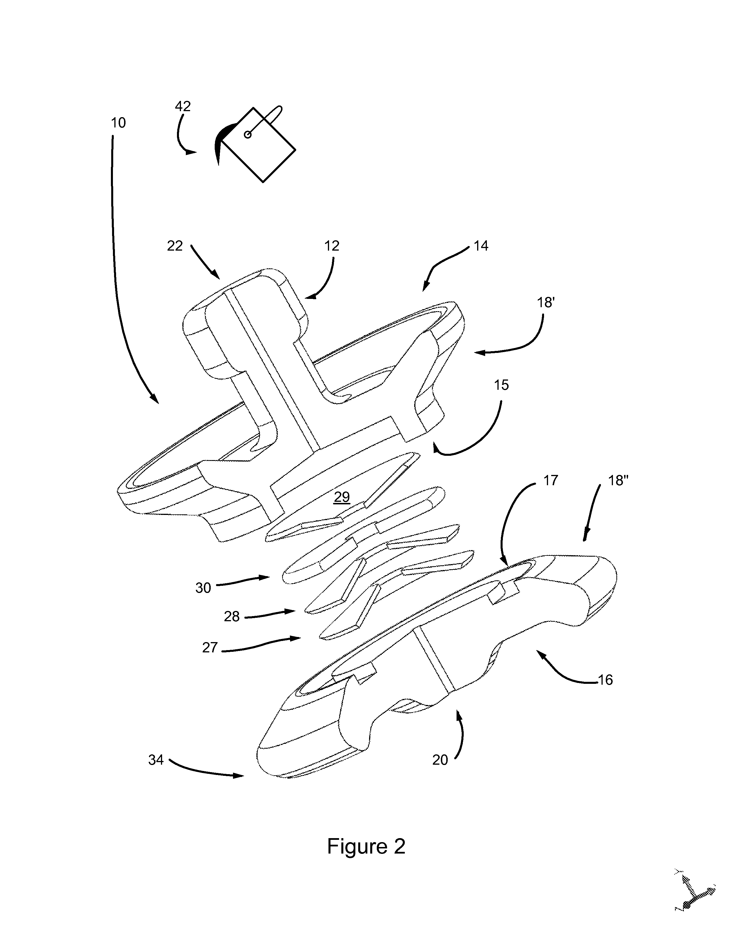
[0044]In the above first invention embodiment, an impulse tolerant valve assembly 10 (see FIGS. 1 and 2) is described as comprising a valve body 14 / 16 which has a longitudinal axis and comprises an elastic valve body base plate 16 and a proximal valve body portion 14. A valve seat interface 34 is located peripherally on the elastic valve body base plate 16. A central internal cavity 19 (see FIG. 3) is substantially enclosed by the valve body base plate 16 and the proximal valve body portion 14, and the valve body has at least one peripheral seal-retention groove 18 and at least one guide 12. The central internal cavity 19 substantially encloses a nonlinear spring-mass damper 27 / 28 / 29 / 30.

[0045]FIGS. 1 and 2 show schematic exploded views of a nonlinear spring-mass damper 27 / 28 / 29 / 30, which is further described below. Belleville springs 27 / 28 / 29 are nonlinear and couple mass 30 to the valve body base plate 16 and the proximal valve body portion 14. Additionally, dilatant liquid 42 (see...


PUM


Abstract

An impulse tolerant valve assembly comprises a valve body having a longitudinal axis and a central internal cavity, the cavity enclosing a nonlinear spring-mass damper optionally immersed in a dilatant liquid. The central internal cavity is enclosed by a proximal valve body portion and a distal elastic valve body base plate, the base plate having a peripheral valve seat interface. Impulse tolerance results in part from hysteresis heat loss due to compliance of the elastic valve body base plate, as well as from heat loss associated with operation of the nonlinear spring-mass damper. The combined heat loss is reflected in reduction of closing energy impulse amplitude and damping of induced valve body vibrations. Compliance of the elastic valve body base plate increases closing energy impulse duration and narrows the corresponding induced vibration spectrum. The valve body has at least one guide and at least one peripheral seal-retention groove.

Description

[0001]This application is a continuation-in-part of copending application Ser. No. 13 / 228,475 filed 9 Sep. 2011, incorporated by reference.FIELD OF THE INVENTION[0002]The invention relates generally to reciprocating high-pressure pumps, and more specifically to the valves of such pumps.BACKGROUND[0003]Reciprocating high-pressure pumps used in oil and gas fields, particularly those intended for fracking, are usually designed in two sections. The (proximal) power section (herein “power end”) and the (distal) fluid section (herein “fluid end”) are often truck-mounted for easy relocation from well-to-well. The fluid end comprises a housing incorporating one or more functional units, each functional unit typically comprising a suction valve, a discharge valve, and a plunger or piston bore in which a reciprocating plunger or piston alternately produces suction strokes and pressure strokes. Such pumps are being operated at unprecedented peak pumped-fluid pressures in current practice (e.g....

Claims


Application Information

Patent Timeline
Patent Type & Authority Patents(United States)
IPC IPC(8): F16K31/00
CPCF16K1/36Y10T137/7868B33Y80/00
Inventor GILSTAD, DENNIS W.GILSTAD, BARBARA C.
Owner GILSTAD DENNIS W
Learn More