Transflective electrophoretic display device

a display device and electrophoretic technology, applied in the field of transmissive electrophoretic display devices, can solve the problems of low display quality, light leakage, and inability to adapt to portable devices, and achieve the effect of enhancing display quality and reducing power consumption

Active Publication Date: 2008-03-04
IND TECH RES INST
View PDF4 Cites 42 Cited by
  • Summary
  • Abstract
  • Description
  • Claims
  • Application Information

AI Technical Summary

Benefits of technology

[0017]A transflective electrophoretic display device is provided for illuminating with or without surrounding light. A light emitted from a backlight module can be adjusted according to the condition of the surrounding light so as to reduce power consumption and enhance the quality of the display.
[0018]The transflective electrophoretic display device is composed of a plurality of display cells, the display device comprises a top substrate, which is a transparent substrate having a plurality of anisotropic reflective plates; a bottom substrate having a plurality of light plates and a plurality of electrodes so as to generate an electric field, and the bottom substrate is installed opposite to the top substrate; a plurality of partitioning walls, which are transparent materials are disposed between the top substrate and the bottom substrate so as to isolate the plurality of display cells; a display solution, which is composed of a plurality of pigment particles and transparent liquid to fill a space isolated by the top substrate, the bottom substrate and the partitioning walls. Wherein, the electric field in the display cell is changed to guide the behavior of the plurality of charged pigment particles in the display solution, a light emits to the anisotropic reflective plates of the top substrate through the partitioning walls, and the plates reflect the light to the display solution so as to radiate monochromatic or gray-scale effects.
[0019]The transflective electrophoretic display device is composed of a plurality of display cells, and each display cell is further composed of a plurality of sub-display cells having red, green and blue colors. The display device comprises a top substrate, which is a transparent substrate having a plurality of anisotropic reflective plates; a bottom substrate having a plurality of light plates and a plurality of electrodes so as to generate an electric field, and the bottom substrate is installed opposite to the top substrate; a plurality of partitioning walls, which are transparent materials and disposed between the top substrate and the bottom substrate so as to isolate the plurality of sub-display cells; a red display solution, a green display solution and a blue display solution which are composed of a plurality of pigment particles and transparent liquids so as to fill a space isolated by the top substrate, the bottom substrate and the partitioning walls. Wherein, the electric field in the display cell is changed to guide the behavior of the plurality of charged pigment particles in the red, green, and blue display solution, a light emits to the anisotropic reflective plates of the top substrate through the partitioning walls, and the reflective plates reflect the light to the red, green and blue display solution so as to radiate color effects.

Problems solved by technology

Moreover, the transmissive-type electrophoretic displayer is not adaptable to portable devices since it consumes a lot of power.
Some drawbacks are associated with the technology having partitioning walls in the prior art provided by the SiPix Imaging, Inc.
Since the partitioning walls 109 are used as the medium for the backlight, this allows the electrophoretic displayer to operate in the dark, but the partitioning walls may possibly cause light leakage.
Moreover, the backlight doesn't go through the display solvent directly, so it doesn't provide a quality of high display.
Meanwhile, the electrophoretic displayer includes both the reflective-type and the transmissive-type, so it has complicated design and is difficult to fabricate.

Method used


Image

  • Transflective electrophoretic display device
  • Transflective electrophoretic display device
  • Transflective electrophoretic display device

Examples


first embodiment

[0050]FIG. 4A and FIG. 4B show the present invention in a white state. The display cell 300 includes a top substrate 401 with a transparent material, a bottom substrate 402 having an electrode structure installed on the other side of the top substrate 401, and a space isolated by the partitioning walls 405. A plurality of anisotropic reflective plates 403 are installed along the top substrate 401 relative to the positions of the partitioning walls 405. The electrodes with in-plane switching mode are disposed in the bottom substrate 402 or even the top substrate 401 so as to generate an in-plane electric field. A black absorbing plate 404 of the preferred embodiment is installed along the bottom substrate 402 excluding the area where the partitioning walls 405 contact the bottom substrate. The aforementioned partitioning walls 405 are transparent, and a light source (not shown in this diagram) is set below the display cell 300. A backlight from the light source is emitted to the anis...

second embodiment

[0057]The structure of the display cell of the second embodiment shown in FIG. 6A is similar to the structure in FIG. 4A. Wherein a space of the display cell is isolated by the partitioning walls 405 between the top substrate 401 and the bottom substrate 402. The space is filled with a display solution 608 having a plurality of black particles 606 and a transparent liquid. The plurality of anisotropic reflective plates 403 is disposed along the top substrate 401 excluding the area where the partitioning walls 405 contact the top substrate 401. The electrodes can be installed on the top or bottom substrate, and thereby the electric field is generated accordingly. The absorbing or reflective plates, such as the reflective plate 604 shown in the diagram, are disposed along the bottom substrate 402 excluding the area where the partitioning walls 405 contact the bottom substrate 402. A light source set below the display cell emits through the gap 407 of the reflective plate 604 and goes ...

third embodiment

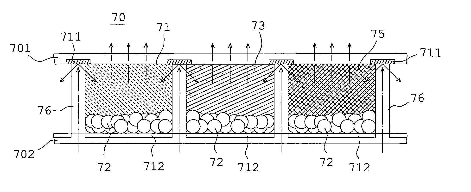
[0063]FIGS. 7A, 7B and 7C are the lateral view of the present invention. The color display cell 70 includes the top substrate 701 with a transparent material, the bottom substrate 702 with electrodes disposed along the bottom substrate 702 opposite to the top substrate 701, a micro-structure space isolated by the partitioning walls 76. The color display cell 70 displays color effects using the sub-display cells having the three primary colors, red, green and blue. Otherwise, the electrodes disposed in the top substrate 701 and the bottom substrate 702 can generate an up / down switching mode, an in-plane switching mode or the a dual switching mode.

[0064]An absorbing or reflecting plate, such as the black absorbing plate of this embodiment, is installed along the bottom substrate 702 excluding the area where the partitioning walls 76 contact the bottom substrate 702. The partitioning walls 76 thereof are transparent, and the light source is disposed below the color display cell 70. The...


PUM

PropertyMeasurementUnit
areaaaaaaaaaaa
areaaaaaaaaaaa
transparentaaaaaaaaaa

Abstract

A transflective electrophoretic display device is disclosed. The device is comprised of a transparent top substrate and both top and bottom substrates have an electrode structure. A plurality of separated walls and an electrophoretic display solution including a plurality of chromatic particles and a transparent liquid are imposed between the two substrates. A device with a display liquid or a filter plate is used to generate a variety of lights such as monochromatic, color-level or true color having a mixture of red, green and blue. The device of the present invention integrates the merits of the reflective and transmitted displayer, and can be used outdoors, indoors or in darkness. Otherwise, a back light module can compensate for the contrast of the displayer effectively.

Description

BACKGROUND OF THE INVENTION[0001]1. Field of the Invention[0002]A transflective electrophoretic display device is disclosed, and more particularly, a device employing a plurality of color particles affected by an electric field is introduced to display monochrome or color images.[0003]2. Description of Related Art[0004]A electrophoretic display device, which comprises a plurality of charged particles controlled by a provided electric field, displays by changing reflectivity in a display region therein relative to a surrounding light. The display device has the following features: (1) it's flexible; (2) it incorporates the surrounding light to improve visibility; (3) it can be manufactured by roll-to-roll process, so it has a high yield and reduces the yielding cost; (4) since there is no limit to the viewing angle, the device can be seen from any point of view; (5) it's not sensitive to the distance variation between two panels; (6) the electrophoretic display device has bistability...

Claims


Application Information

Patent Timeline
Patent Type & Authority Patents(United States)
IPC IPC(8): G02B26/00G09G3/34G02F1/167G02F1/1677
CPCG02F1/133377G02F1/167G02F2203/09G02F1/1677
Inventor DING, JAU-MINLIAO, CHI-CHANGJENG, SHIE-CHANGCHEN, YI-CHENGLU, CHIH-CHIANG
Owner IND TECH RES INST
Why Eureka
Try Eureka