Method for wedge time shift calibration in a disk drive

a technology of disk drive and wedge, applied in the field of disk drive, can solve problems such as problems such as the problem of measuring the time between servo wedges

Inactive Publication Date: 2008-03-04
WESTERN DIGITAL TECH INC
View PDF15 Cites 113 Cited by
  • Summary
  • Abstract
  • Description
  • Claims
  • Application Information

AI Technical Summary

Problems solved by technology

However, measuring the time between servo wedges may be problematic during a high-speed seek.

Method used


Image

  • Method for wedge time shift calibration in a disk drive
  • Method for wedge time shift calibration in a disk drive
  • Method for wedge time shift calibration in a disk drive

Examples


Embodiment Construction

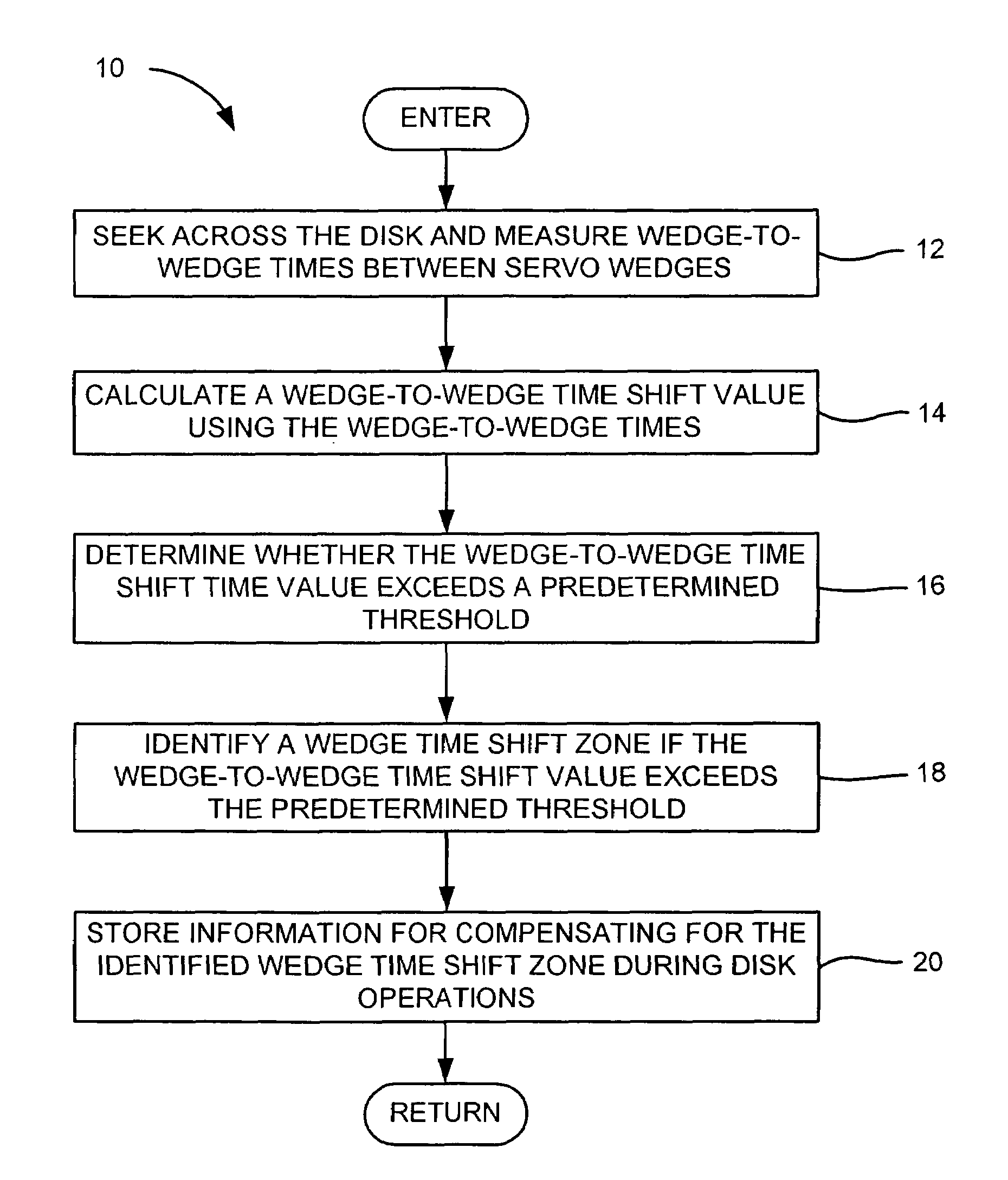
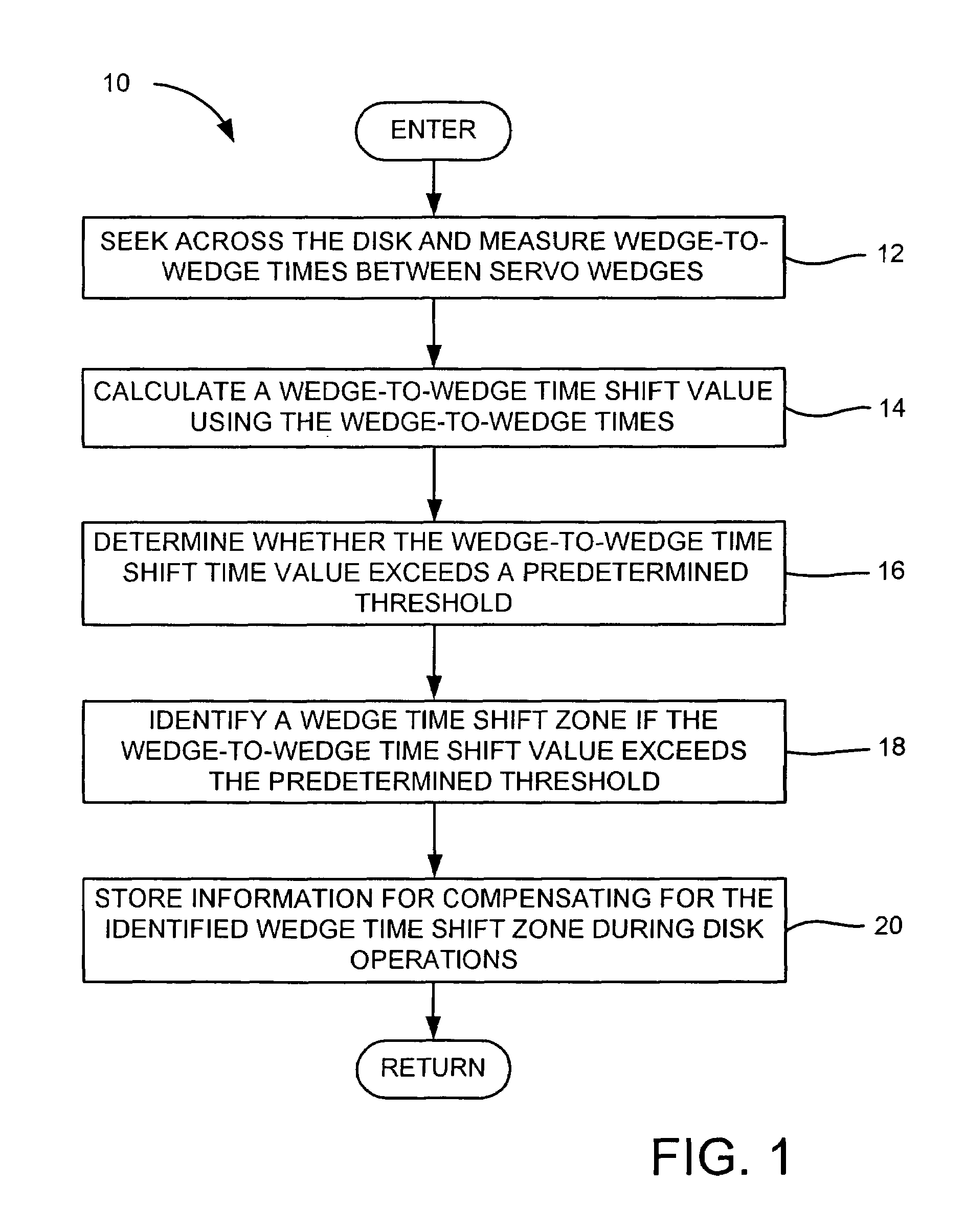
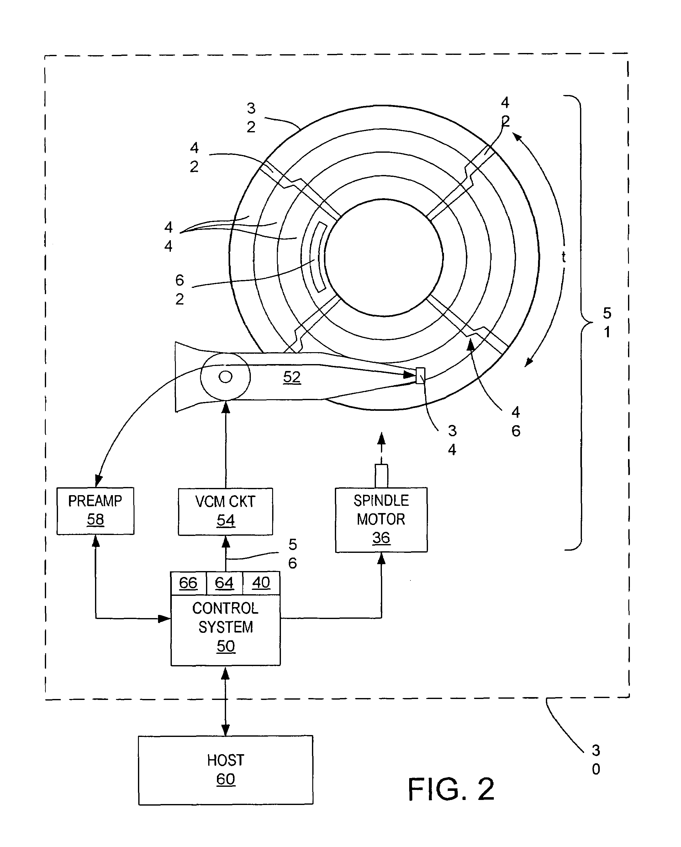
[0016]With reference to FIGS. 1 and 2, the present invention may be embodied in a method 10 (FIG. 1) for wedge time shift calibration in a disk drive 30 (FIG. 2). The disk drive includes a disk 32, a head 34 actuated over the disk, and a spindle motor 36. The spindle motor rotates the disk at an operating speed in response to a spindle control current generated by a spindle control system 40. The disk has a plurality of spaced-apart embedded servo wedges 42 that define a plurality of concentric data tracks 44. In the method, wedge-to-wedge times t between servo wedges are measured during a seek across the disk (step 12). A wedge-to-wedge time shift value is calculated using the wedge-to-wedge times (step 14). If the wedge-to-wedge time shift value exceeds a predetermined threshold (step 16), then a wedge time shift zone 46 is identified (step 18), and information is stored for compensating for the identified wedge time shift zone during disk operations (step 20).

[0017]The method 10 ...


PUM

PropertyMeasurementUnit
time shift timeaaaaaaaaaa
time shiftaaaaaaaaaa
timeaaaaaaaaaa

Abstract

A method is disclosed for identifying wedge time shift zones on a magnetic disk of a disk drive. The disk drive further includes a spindle motor for rotating the disk at an operating speed in response to a spindle control current generated by a spindle control system, and a head that is actuated over the disk. During operation, the control systems causes a seek of the head across the disk and measures wedge-to-wedge times between servo wedges. The control system then calculates a wedge-to-wedge time shift value using the wedge-to-wedge times and determines whether the wedge-to-wedge time shift time value exceeds a predetermined threshold. If the wedge-to-wedge time shift value exceeds the predetermined threshold, then the control system identifies a wedge time shift zone, and stores information for compensating for the identified wedge time shift zone during disk operations.

Description

BACKGROUND OF THE INVENTION[0001]1. Field of the Invention[0002]The present invention relates to disk drives, and more particularly, to wedge time shift calibration in a disk drive for improved disk rotation rate regulation.[0003]2. Description of the Prior Art and Related Information[0004]In order to remain competitive, disk drive manufacturers must continually provide increased data storage capacity and access rate while rigidly controlling disk drive manufacturing cost. One key to increased data access rate is increased disk rotation rate. The disk is rotated at a constant angular velocity by a spindle motor in response to a spindle control current. The spindle motor current may be generated based on a measured time between servo wedges on the disk. However, measuring the time between servo wedges may be problematic during a high-speed seek.[0005]Accordingly, there exists a need for a calibration technique that allows for improved regulation of a disk's rotation rate during a hig...

Claims


Application Information

Patent Timeline
Patent Type & Authority Patents(United States)
IPC IPC(8): G11B5/596G11B5/09
CPCG11B5/59616G11B5/5534
Inventor TU, KUANG-YANGLI, JOHN YIN KWONG
Owner WESTERN DIGITAL TECH INC
Why Eureka
Try Eureka