Combination structure of a zipper head

a zipper head and combination structure technology, applied in the direction of snap fasteners, slide fasteners, press-button fasteners, etc., can solve the problem of insufficient stopping force, and achieve the effect of low manufacturing cost and easy manufacturing and fabrication

Active Publication Date: 2008-03-11
CHUNG CHWAN ENTERPRISE CO LTD
View PDF4 Cites 2 Cited by
  • Summary
  • Abstract
  • Description
  • Claims
  • Application Information

AI Technical Summary

Benefits of technology

[0009]It is a primary object of the present invention to provide a combination structure of a zipper head that provides a reasonable stopping force via the stopping portion while keeping manufacturing costs low as possible, and allows the zipper head to be easily manufactured and fabricated.

Problems solved by technology

This often provides insufficient stopping force.

Method used


Image

  • Combination structure of a zipper head
  • Combination structure of a zipper head
  • Combination structure of a zipper head

Examples


Embodiment Construction

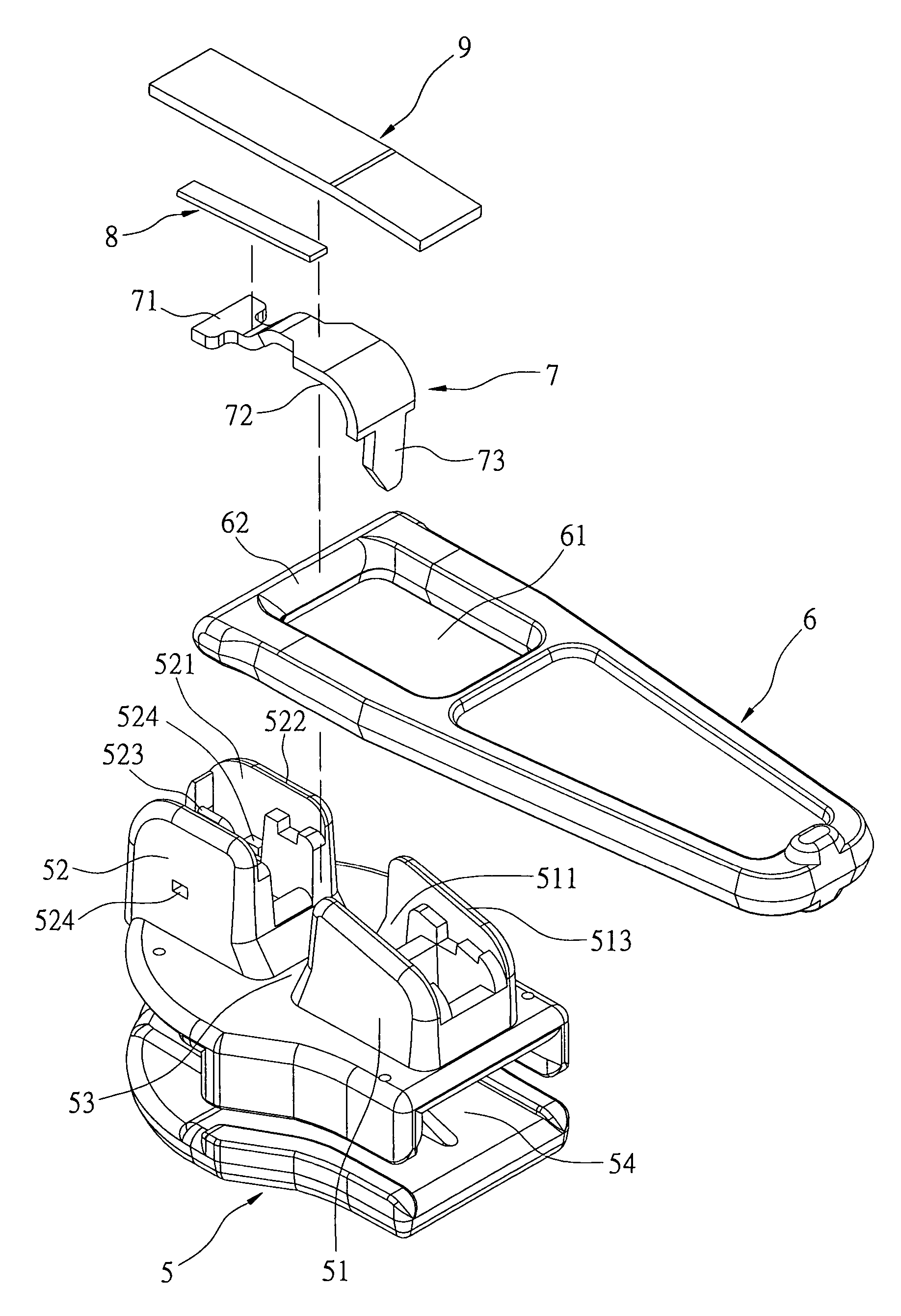
[0019]Reference is made to FIGS. 3 to 5. The combination structure of a zipper head of the present invention comprises a zipper head 5, a pull tag 6, a pin lock 7, a spring piece 8, and a cover plate 9. The zipper head 5 has a first fixing base 51 and a second fixing base 52 mounted thereon. A sunken space 53 is formed between the first fixing base 51 and the second fixing base 52, a groove 511 and a groove 521 are separately disposed on an opposite side of the first fixing base 51 and the second fixing base 52, and a pin locking hole 512 is installed in the groove 511 of the first fixing base 51. A pull tag 6 has a receiving hole 61 in one end thereof, and an end portion 62, coupled with the rear edge of the receiving hole 61, is installed in the sunken space 53 of the zipper head 5.

[0020]A pin lock 7 has a head portion 71 at one end thereof firmly installed in the groove 521 of the second fixing base 52. The groove 521 of the second fixing base 52 has two walls that are separately...


PUM


Abstract

A combination structure of a zipper head of the present invention comprises a zipper head, a pull tag, a pin lock, a spring piece, and a cover plate, wherein three components, the pin lock, the spring piece, and the cover plate, are composed of different materials and are mutually independent. Such a structure is different from the integrated structure of combining the above three components of the conventional invention. Hence the combination structure of the zipper head of the present invention provides sufficient stopping force via the stopping portion whilst being cheaper to produce, and easily manufactured and fabricated.

Description

BACKGROUND OF THE INVENTION[0001]1. Field of the invention[0002]The present invention relates to a combination structure of a zipper head, and more particularly to the combination structure of a zipper head that has a pin lock, a spring piece, and a cover plate.[0003]2. Description of the Prior Art[0004]Reference is made to FIG. 1 and FIG. 2. The combination structure of a zipper head of the prior art comprises a zipper 1, a pull tag 2, and a spring piece 3. The sequence of the fabrication of the conventional combination structure of a zipper head involves the end portion 22 of the pull tag 2 being installed in the sunken space 13 of the zipper head 1, and then the pull tag 2 is pushed to one end of the zipper head 1 so that the first fixing base 11 or the second fixing base 12 of the zipper head 1 is sheathed by means of the receiving hole 21 of the pull tag 2. Next, two ends of the spring piece 3 are separately and firmly mounted on the first fixing base 11 and the second fixing b...

Claims


Application Information

Patent Timeline
Patent Type & Authority Patents(United States)
IPC IPC(8): A44B19/30A44B19/24
CPCA44B19/308Y10T24/2571Y10T24/2577
Inventor LIN, YU-PAU
Owner CHUNG CHWAN ENTERPRISE CO LTD
Why Eureka
Try Eureka