
H-shaped Vertical Axis Type Windmill Structure

a vertical axis type, windmill technology, applied in vessel construction, sustainable manufacturing/processing, greenhouse gas reduction, etc., can solve the problems of prolonging the service life of the windmill, and achieve the effects of low production cost, high strength, and easy manufacture and fabrication

Inactive Publication Date: 2009-12-03
ENERGY TECH
View PDF1 Cites 4 Cited by
  • Summary
  • Abstract
  • Description
  • Claims
  • Application Information

AI Technical Summary

Benefits of technology

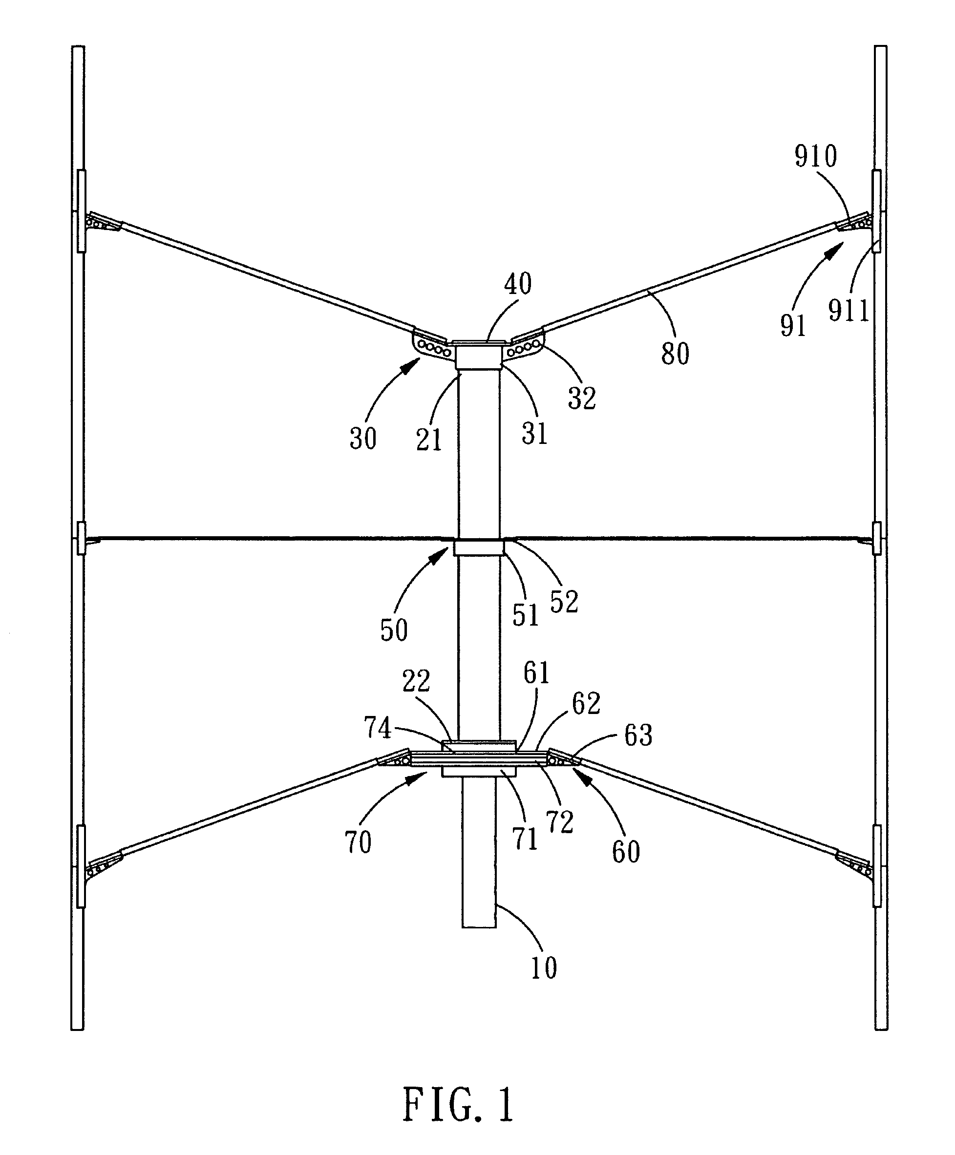
[0006]The primary objective of the present invention is to provide a H-shaped vertical axis type windmill which comprises rotary shaft, connecting arms and vertical blades which are assembled together to form a H-shaped windmill structure, with such a design, the blades can be of flat and straight shape, so as to achieve the purpose of easy manufacture and fabrication, low production cost, and high strength.
[0007]Another objective of the present invention is to provide an H-shaped vertical axis type windmill, with the arrangement of a connecting member, a support base and a support bracket that have different elevation angles between the connecting arms connected with the blades and the rotary shaft, different sized blades, no matter large, middle or small, all can be effectively supported. Therefore, different shaped and sized windmill structures can be assembled, improving the applicability of the present invention.
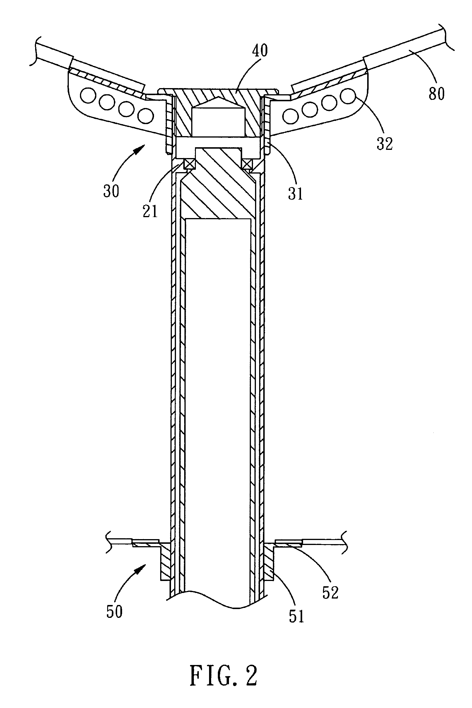
[0008]Yet another objective of the present invention is to provide an H-shaped vertical axis type windmill, wherein the mainshaft received in the rotary shaft cooperates with a bearing to ensure the smooth rotation of the rotary shaft with respect to the mainshaft, and cooperates with the generator to ensure effective operation. Furthermore, since the vertically arranged blades reduce the unnecessary deviation during rotation, so that the frication damage caused by inappropriate deviation of the blades can be reduced. The high stability of rotation effectively prolongs the service life of the windmill.

Problems solved by technology

The high stability of rotation effectively prolongs the service life of the windmill.

Method used


Image

  • H-shaped Vertical Axis Type Windmill Structure
  • H-shaped Vertical Axis Type Windmill Structure
  • H-shaped Vertical Axis Type Windmill Structure

Examples


Embodiment Construction

[0017]The present invention will be clearer from the following description when viewed together with the accompanying drawings, which show, for purpose of illustrations only, the preferred embodiment in accordance with the present invention.

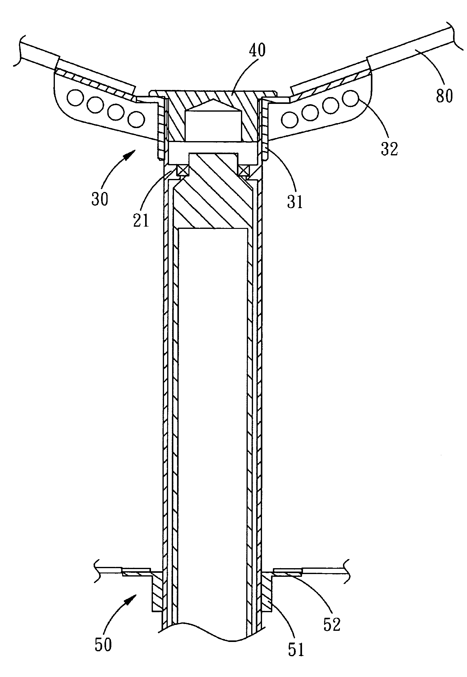
[0018]Referring to FIGS. 1-5, a H-shaped vertical axis type windmill structure in accordance with a preferred embodiment of the present invention is shown and comprises a stationary mainshaft 10 on the top end of which is disposed a rotary shaft 20, and on the top end of the rotary shaft 20 is disposed a support bracket 30 in the form of a multi-branched structure. The center of the support bracket 30 is covered with a cover 40. A multi-branched connecting member 50 is mounted on the middle of the rotary shaft 20, and a multi-branched support base 60 is disposed at the bottom of the rotary shaft 20. Between the support base 60 and the mainshaft 10 is disposed a bearing assembly 70 for cooperating with bearing structures between the mainshaft 10 a...


PUM


Abstract

An H-shaped vertical axis type windmill structure comprises a mainshaft on the top end of which is disposed a rotary shaft by a bearing. On the top and lower ends of the rotary shaft are disposed a support bracket and a support base, and in the middle of the rotary shaft is a connecting member. The support bracket, support base and the connecting member are connected to the connecting arms, and the other ends of the connecting arms are fixed to vertical blades. The connecting arms enable the blades to be vertically connected with the rotary shaft, and the mainshaft is not rotatable and serves as a stator of the generator structure. The vertically arranged straight and flat blades are easy to manufacture and fabricate and can be made of composite material for purpose of lightweight.

Description

BACKGROUND OF THE INVENTION[0001]1. Field of the Invention[0002]The present invention relates to an H-shaped vertical axis type windmill structure which is a combined structure of a wind generator and its drive device, and more particularly to an H-shaped vertical axis type windmill whose blades are maintained in a vertical and straight state.[0003]2. Description of the Prior Art[0004]Windmills are generally divided into vertical type and horizontal type according to their blades' arrangement. The horizontal type, for example, is the helicopter airfoil like windmill which is often seen in Taiwan, the generator of this type of windmill is horizontally arranged, and its blades are vertically arranged in the same way as the helicopter airfoil. The vertical windmill includes Darrieus and Savonius types, and the generator of the vertical windmill is vertically arranged. The applicant of the application has made an improvement to the Darrieus windmill in his earlier TW Pt No. M310590 “imp...

Claims


Application Information

Patent Timeline
Patent Type & Authority Applications(United States)
IPC IPC(8): F03D3/00F04D29/046
CPCF03D3/065Y02E10/74F05B2240/214Y02P70/50F03D3/062
Inventor CHEN, MING-KUOHSIEH, ALLENCHEN, JACKENKAO, JASON
Owner ENERGY TECH
Learn More