
Recuperative heater for an external combustion engine

Inactive Publication Date: 2005-09-01
SUMA ALGEBRAICA
View PDF10 Cites 3 Cited by
  • Summary
  • Abstract
  • Description
  • Claims
  • Application Information

AI Technical Summary

Benefits of technology

[0026] By incorporating the exhaust gas heat exchanger in an engine according to the above configuration, numerous advantages are realised.
[0027] Firstly, virtually all the heat generated in the combustion portion can flow into the exchanger fluid and thereby increasing efficiency of energy recovered from the fuel significantly.
[0028] Secondly, as the heat exchanger may be formed as a rigidly fixed portion of the engine structure, there is no requirement for a flexible coupling between the heat exchanger and the combustion products outlet from the combustion portion. This can reduce manufacturing and system costs and complexity, whilst improving reliability.
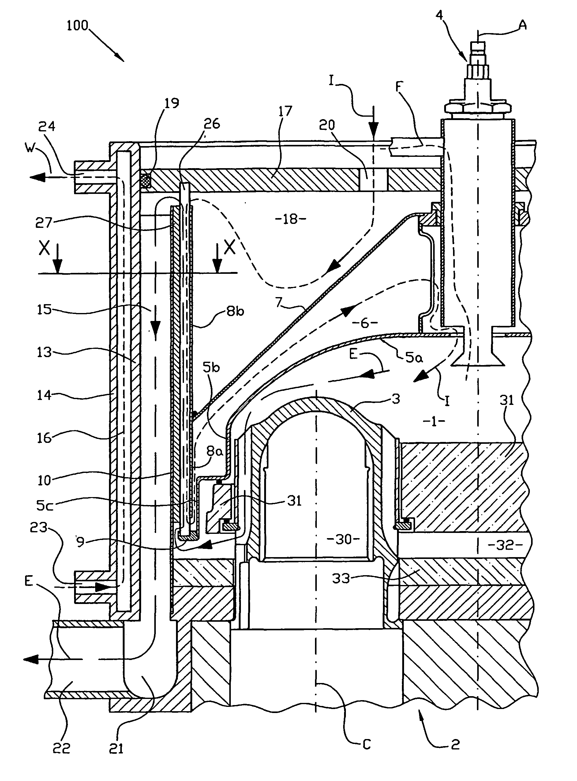
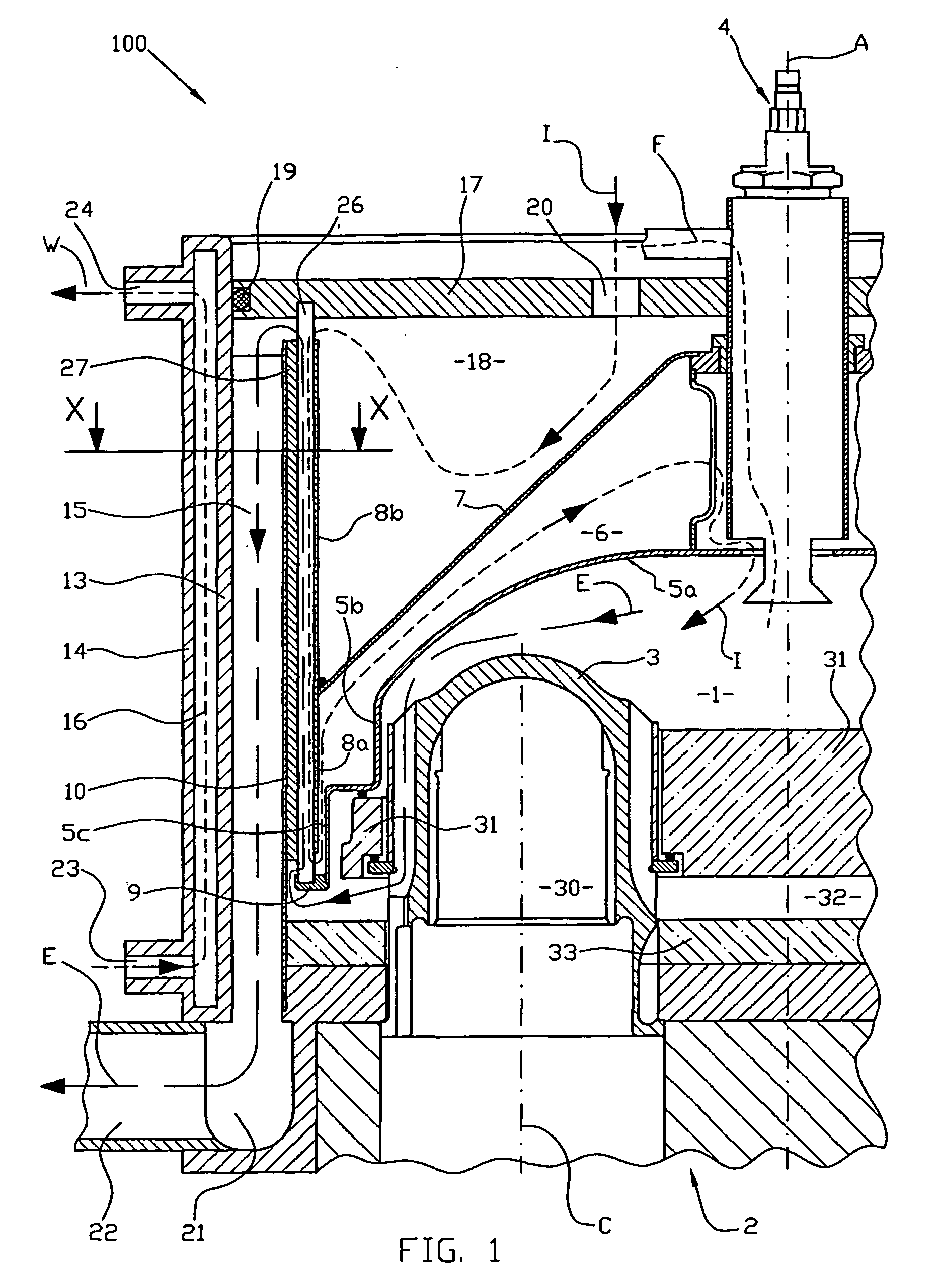
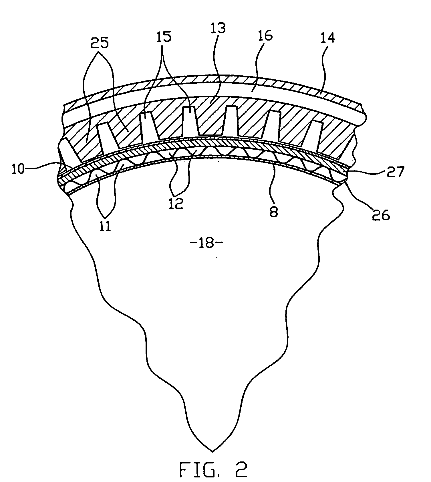
[0041] Preferably the exhaust gas heat exchanger includes an exhaust gas passage adjacent to a jacket for receiving the fluid, the jacket at least partially surrounding both the combustion chamber and the recuperative heat exchanger. By at least partially surrounding the combustion chamber and the recuperative heat exchanger, the fluid in the jacket is able to absorb heat that my otherwise be lost. The fluid is preferably a liquid (e.g. water) circulated through the jacket. The exhaust gas heat exchange takes place during a single axial pass, before the combustion products pass to the flue. Preferably this single pass approximates a contra-flow action with the fluid flow through the jacket. The combustion products preferably pass in a cylindrical passage adjacent the inner wall of the jacket. Means are provided for improving the heat transfer from the combustion products, preferably comprising fins formed in the inner wall of the water jacket and projecting into the exhaust gas passage.
[0046] Most preferably the heater is installed on a Stirling engine forming part of a cogeneration system for providing heat and electricity, the engine driving an electrical generator and supplying a liquid heated by the engine and the exhaust gas heat exchanger to a heating circuit. Alternatively, the heater may be used in other external combustion engines for providing improved energy efficiency within a single compact device.
[0047] The heater is compact and may be readily fabricated. Without external insulation, all the outer components present no danger of burning the user, the water jacket cooling the sides and the plenum arrangement cooling the top cover. It is effective and efficient in operational use, may be economically constructed and has an overall simple design that minimizes manufacturing costs and maximizes performance, and simplifies maintenance by offering an essentially modular design.

Problems solved by technology

However, this type of configuration poses disadvantages in this and other systems utilizing a conventional exhaust gas heat exchanger.
The disadvantages largely stem from the incorporation of the heat exchanger as a subsequent addition to the engine rather than as an integral engine design element.
In particular, disadvantages in conventional systems include: The heat exchanger requires connection to the engine exhaust via some form of coupling or duct.
The complexity and cost of producing a reliable exhaust coupling are increased by the harsh environmental conditions including the effects of corrosive high temperatures exhaust gases.
Heat is lost directly from the coupling.
The inherent design constraints of a non-integrated flexible exhaust coupling hinder the efficient prevention of heat losses.
Increased manufacturing and operational system complexity and thus cost.

Method used


Image

  • Recuperative heater for an external combustion engine
  • Recuperative heater for an external combustion engine
  • Recuperative heater for an external combustion engine

Examples


Embodiment Construction

[0053] Referring to FIGS. 1 and 2, a first preferred embodiment of the recuperative heater 100 of the present invention is installed on a Stirling engine 2.

[0054] It will be appreciated that while a Stirling engine is shown in the preferred embodiment, the present invention is not necessarily restricted to same. It can be seen by one skilled in the art that the concept of integrating an exhaust heat exchanger into the structure of a combustion engine may be equally applied to internal and external combustion engines. Furthermore, the exact configuration shown in the preferred embodiment is but one example of numerous possible implementations which also fall within the scope of the invention.

[0055] As shown in the drawings, the present invention is integrated into the structure of a Stirling engine 2 having an axis A, with four vertical cylinders 30 in a square arrangement. The principal components of the heater 100 are generally symmetrical about axis A, which extends parallel to ...


PUM


Abstract

A recuperative heater for heating the heater heads of an external combustion machine includes a recuperative heat exchanger having an axial pass section partially surrounding the combustion chamber. Combustion products pass from the recuperative heat exchanger to a condensing exhaust gas heat surrounding the axial pass section and comprising a cylindrical exhaust gas passage ringed externally by a water jacket. Water from the water jacket may be circulated to a thermal load. A top cover of the heater opposes the heater heads or hot end of the engine. Inner and outer plenums are formed between the combustion chamber wall and the top cover and inlet air is heated in stages as its enters the outer plenum, passes into the axial pass section, into the inner plenum, then into the combustion chamber.

Description

TECHNICAL FIELD [0001] The present invention relates generally to a recuperative heater for an external combustion machine, and more particularly to a recuperative heater with an exhaust gas heat exchanger. Most particularly the invention relates to a heater for supplying operating heat to a Stirling engine used in a cogeneration system. BACKGROUND ART [0002] A number of closed-cycle thermodynamic machines operate with heat from a high-grade source, typically in the form of a fossil fuel burner, to directly heat a heat exchanger or heater head integral with the machine. A Stirling engine is an example of such an external combustion thermodynamic machine. [0003] Stirling engines are well suited to cogeneration (or combined heat and power) applications and offer significant potential advantages. Stirling engines have a low emission external combustion system, thereby allowing multiple fuels to be used, preventing internal parts becoming fouled by the combustion products and providing ...

Claims


Application Information

Patent Timeline
IPC IPC(8): F01K23/06F02G1/055F02G1/057F02G5/02F23C7/06
CPCF02G1/055Y02E20/14F02G1/057
Inventor CLUCAS, DONALD MURRAY
Owner SUMA ALGEBRAICA
Learn More