Travelator, moving ramp or escalator

a technology for moving ramps and escalators, which is applied in the direction of escalators, conveyers, transportation and packaging, etc., can solve the problems of belt fatigue, inapplicability of current driving solutions to drive handrail belts in travelators, and high cost of handrail belts manufactured from special materials, etc., to achieve simple and inexpensive, and extend the service life of handrail belts

Active Publication Date: 2008-03-11
KONE CORP
View PDF31 Cites 28 Cited by
  • Summary
  • Abstract
  • Description
  • Claims
  • Application Information

AI Technical Summary

Benefits of technology

[0009]A more specific object of the invention is to provide a simple and inexpensive solution for driving a handrail belt.
[0010]A further object of the invention is to provide a solution for driving a handrail belt that does not cause wear of the handrail belt, thus allowing the service life of the handrail belt to be extended.
[0013]The invention is based on the insight that a handrail belt under normal tension can be driven by utilizing the pressure rollers already existing in the turn-around guide, by passing the drive belt between them and the handrail belt. As the handrail belt is pressed with a sufficient force against the drive belt in the turn-around portion due to its normal tension, it is not necessary to provide any counter-support on the outer side of the handrail belt, thus allowing an inexpensive, simple and compact drive solution to be achieved. A handrail belt manufactured from conventional materials can be used, and its wear is reduced and its service life increased. The drive solution of the invention is particularly well suited for use in travelators, moving ramps or escalators in which the frame is intended to have as low a construction height as possible and which are designed to be mounted on a fixed base without a pit formed in the fixed base.
[0017]In yet another exemplary embodiment of the invention, the deflection roller is placed at the upper end of the sequence of pressure rollers and the driving roller is placed at the lower end of the sequence of pressure rollers. In one advantageous exemplary embodiment, all the existing pressure rollers are utilized, because the larger the contact surface is, the less slippage will there occur between them and therefore the belts will undergo less wear due to slippage. If a sufficient frictional force is achieved, in some applications the drive belt may only be passed over some of the pressure rollers.

Problems solved by technology

The problem is that a handrail belt manufactured from special materials is expensive.
Moreover, the current type of driving solution used to drive the handrail belt is not applicable for use in travelators, moving ramps or escalators in which the frame is intended to have as low a construction height as possible and which are designed to be mounted on a fixed base without a pit formed in the fixed base.
A problem with this solution is that the handrail belt is subject to pressing forces that may cause fatigue of the belt material in the course of time.
The pressure belt contacting the visible outer side of the handrail belt causes wear of the handrail belt.
In addition, in order to achieve a sufficient driving force, the pressure belt and its deflection and pressure rollers are necessarily needed, which leads to a massive and expensive construction.

Method used


Image

  • Travelator, moving ramp or escalator
  • Travelator, moving ramp or escalator
  • Travelator, moving ramp or escalator

Examples


Embodiment Construction

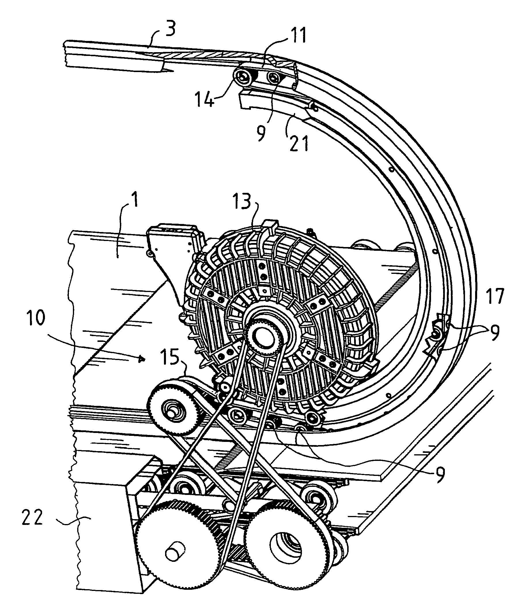
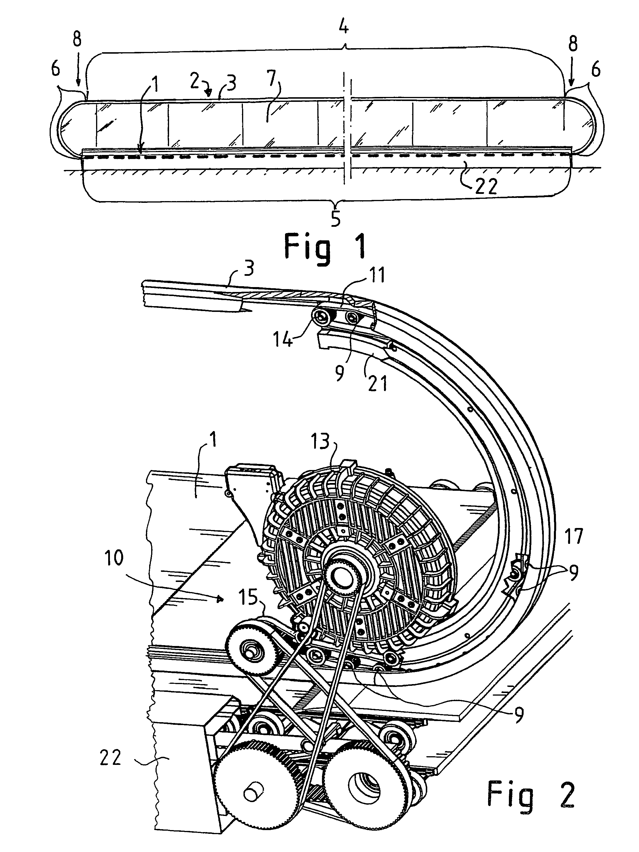
[0030]FIG. 1 presents a travelator of a low construction height, designed to be mounted on a fixed base, such as a floor or other support, which means that no pit has to be made in the fixed base for the travelator machinery. In the following description of an exemplary embodiment, the invention is described with reference to a horizontal travelator, but it is obvious that corresponding principles of the invention can be applied to moving ramps and escalators as well.

[0031]The travelator comprises a people mover 1, which may be any applicable type of conveyor known to the person skilled in the art, e.g. a pallet conveyor or belt conveyor. The people mover 1 is mounted on a conveyor frame 22. The conveyor frame 22 lies on a floor throughout its length. Supported on the conveyor frame 22 are usually two balustrades 2, which extend along both sides of the people mover throughout its length.

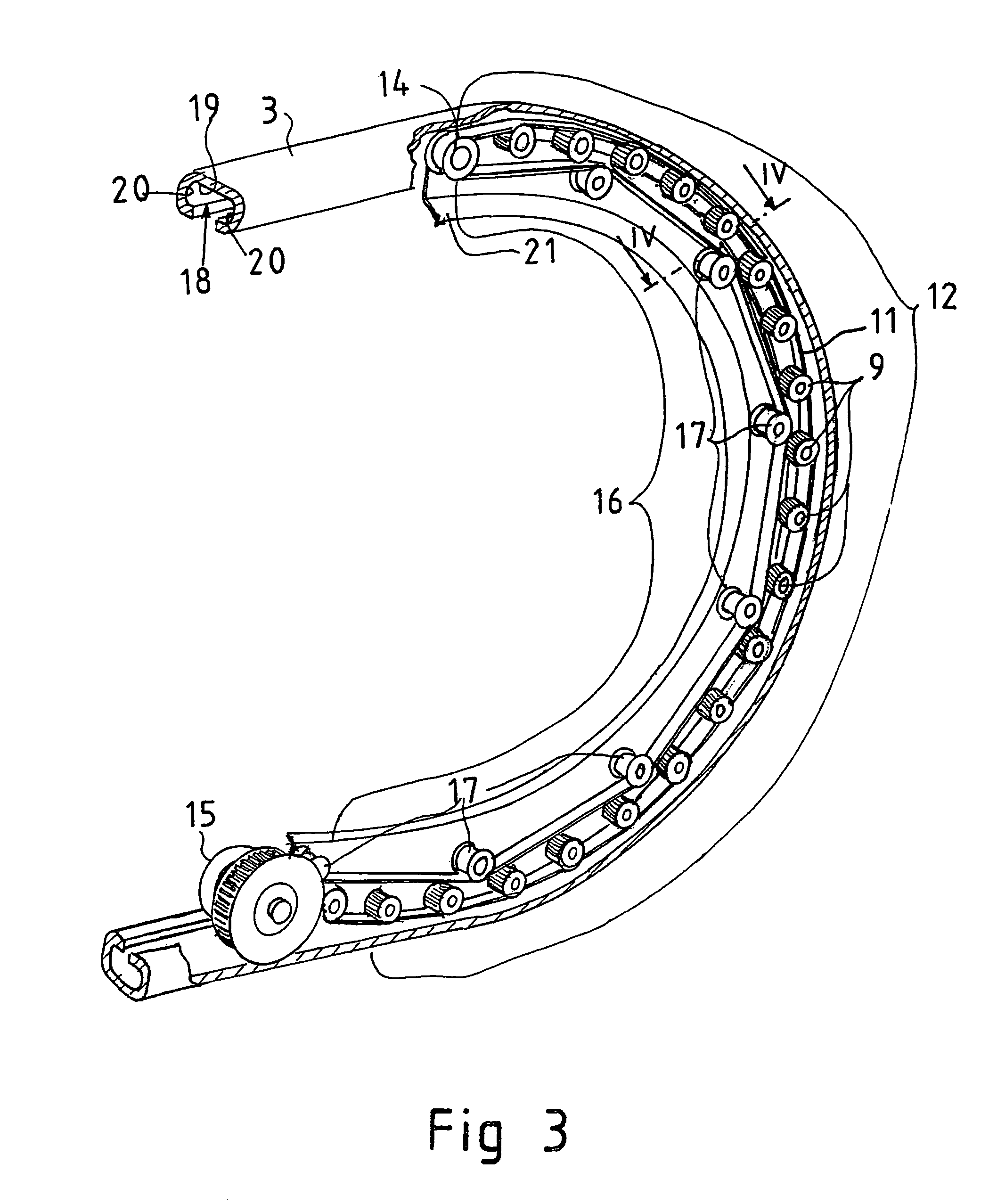
[0032]Each balustrade 2 comprises a handrail belt 3 formed as an endless loop. The visible upper ...


PUM


Abstract

A travelator, moving ramp or escalator for transporting people, comprises a people mover; a balustrade extending alongside the people mover throughout its length. The balustrade comprises a handrail belt formed as an endless loop and having an upper handhold portion, which the passenger can grasp with a hand for support, a lower return portion, and a turn-around portion between the handhold portion and the return portion. The balustrade frame comprises a turn-around guide at the end of the balustrade to form a turn-around to support and guide the turn-around portion of the handrail belt. The turn-around guide comprises a number of pressure rollers spaced at a distance from each other and arranged in a sequence in the form of a circular arc. In addition, a drive assembly is arranged to move the handrail belt. The drive assembly comprises a drive belt formed as an endless loop and having a contact portion which is in driving contact with the handrail belt over a predetermined length, and a power mechanism for driving the drive belt. The contact portion of the drive belt is passed over the sequence of pressure rollers between the pressure rollers and the turn-around portion of the handrail belt.

Description

CROSS-REFERENCE TO RELATED APPLICATIONS[0001]This application is a continuation of International Application No. PCT / FI2005 / 000043 filed Jan. 21, 2005, designating the United States and claiming priority from Application NO. FI20040167 filed in Finland on Feb. 3, 2004. The disclosures of both foregoing applications are incorporated herein by reference along with each and every U.S. and foreign patent and patent application mentioned herein below.BACKGROUND OF THE INVENTION[0002]The present invention relates to a travelator, moving ramp or escalator.[0003]Travelators, moving ramps or escalators wherein people are transported on a conveyor horizontally or at an upward / downward angle are disclosed for example in International Patent Application Publication No. WO 02 / 26612 and U.S. Pat. No. 5,117,960. Such a travelator or escalator comprises a people mover and a balustrade extending alongside the people mover throughout its length. The balustrade comprises a handrail belt implemented as...

Claims


Application Information

Patent Timeline
Patent Type & Authority Patents(United States)
IPC IPC(8): B66B23/04
CPCB66B23/04
Inventor AULANKO, ESKOMUSTALAHTI, JORMAOSSENDORF, MARC
Owner KONE CORP
Why Eureka
Try Eureka