
Aircraft interior wireless communications system

a wireless communication system and aircraft technology, applied in the direction of electrical signalling details, instruments, burglar alarm mechanical actuation, etc., can solve the problems of shrinking the already limited spectral bandwidth and poor radio frequency radiation in the interior of the aircra

Active Publication Date: 2008-03-11
GOODRICH LIGHTING SYST INC
View PDF14 Cites 16 Cited by
  • Summary
  • Abstract
  • Description
  • Claims
  • Application Information

AI Technical Summary

Benefits of technology

"The present invention provides a wireless communication system for use in an aircraft interior, such as a part of a wireless emergency lighting system. The system uses an integrated lens antenna system that takes advantage of the quantity and location of emergency lights to create a virtual network. If the path between any two lights becomes disrupted, alternate paths will be constructed under software control. The invention allows for seamless communication between the controller and the light assemblies, ensuring reliable and efficient communication. The lighting device includes a housing, one or more light generating elements mounted to the housing, and a wireless communication device mounted to the housing. The controller communicates wirelessly with one or more of the plurality of devices. The system can change the wireless communications path between the controller and a given device in response to a disruption between two devices along the given wireless communications path. The technical effects of the invention include improved communication reliability and efficiency, as well as seamless integration with the aircraft's existing emergency lighting system."

Problems solved by technology

While there is a need for wireless communications systems within aircraft, integrating wireless communications systems within aircraft provides a unique set of challenges.
First, the interior of an aircraft is a poor medium for radio frequency (RF) radiation due at least in part to the fact that it is non-uniform and dynamic because of passenger and / or luggage movement.
Also, the already-limited spectral bandwidth is shrinking with the development of new technology devices.

Method used


Image

  • Aircraft interior wireless communications system
  • Aircraft interior wireless communications system
  • Aircraft interior wireless communications system

Examples


Embodiment Construction

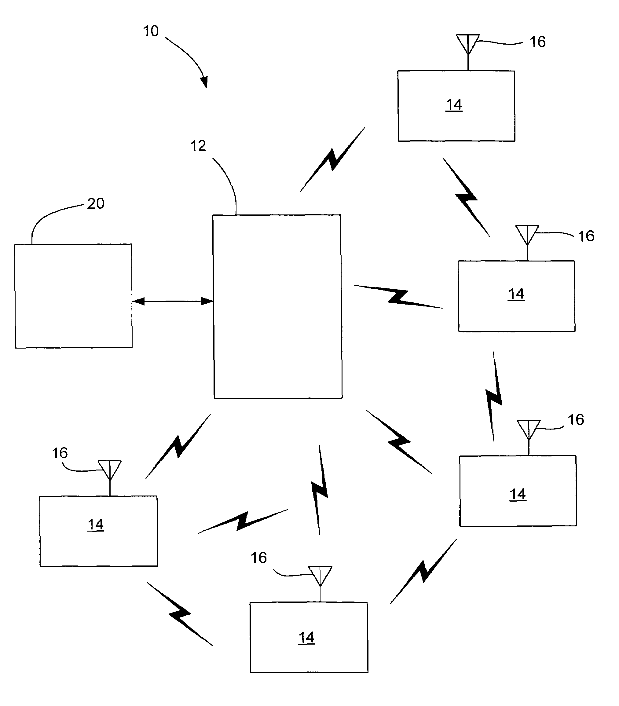
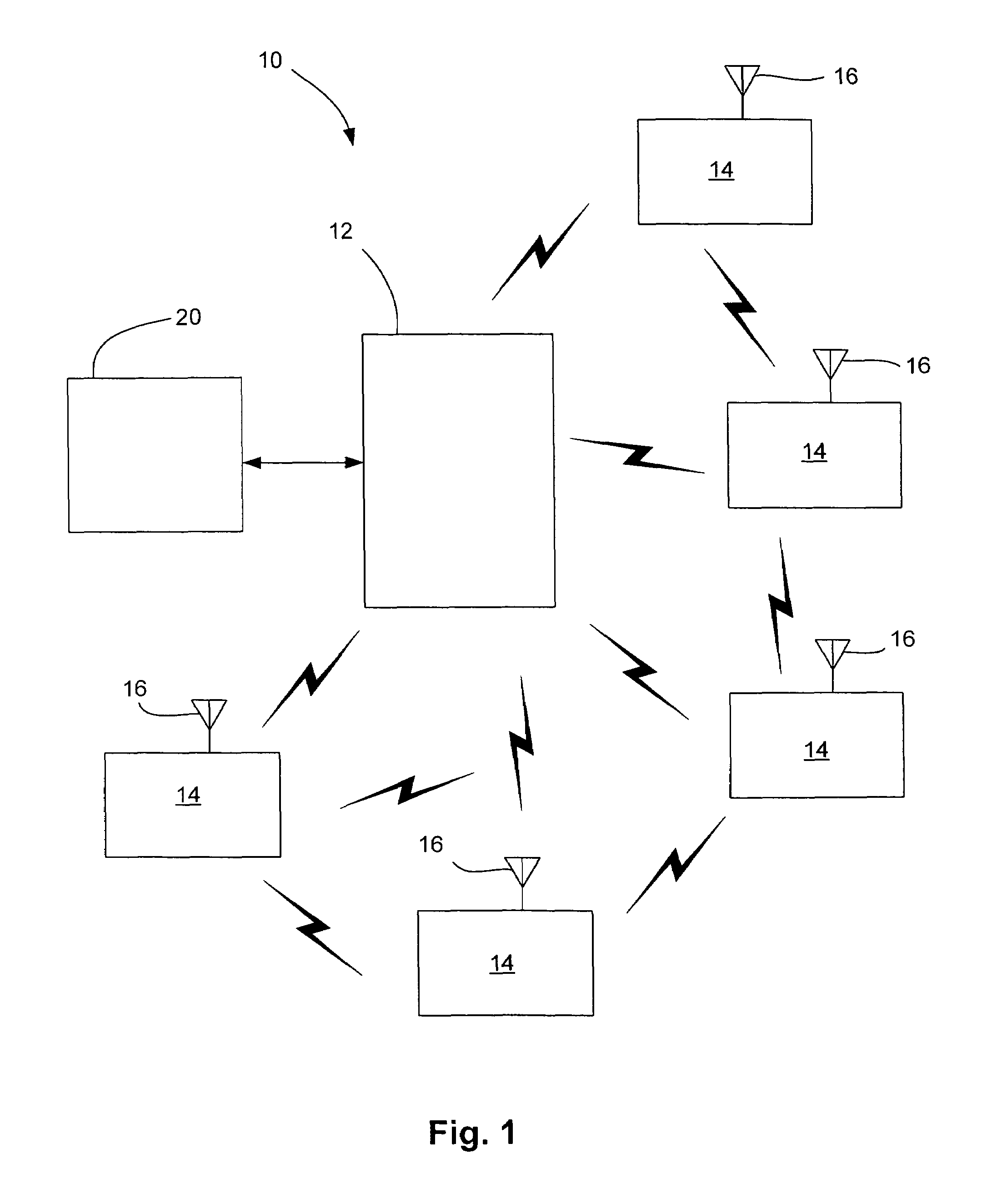
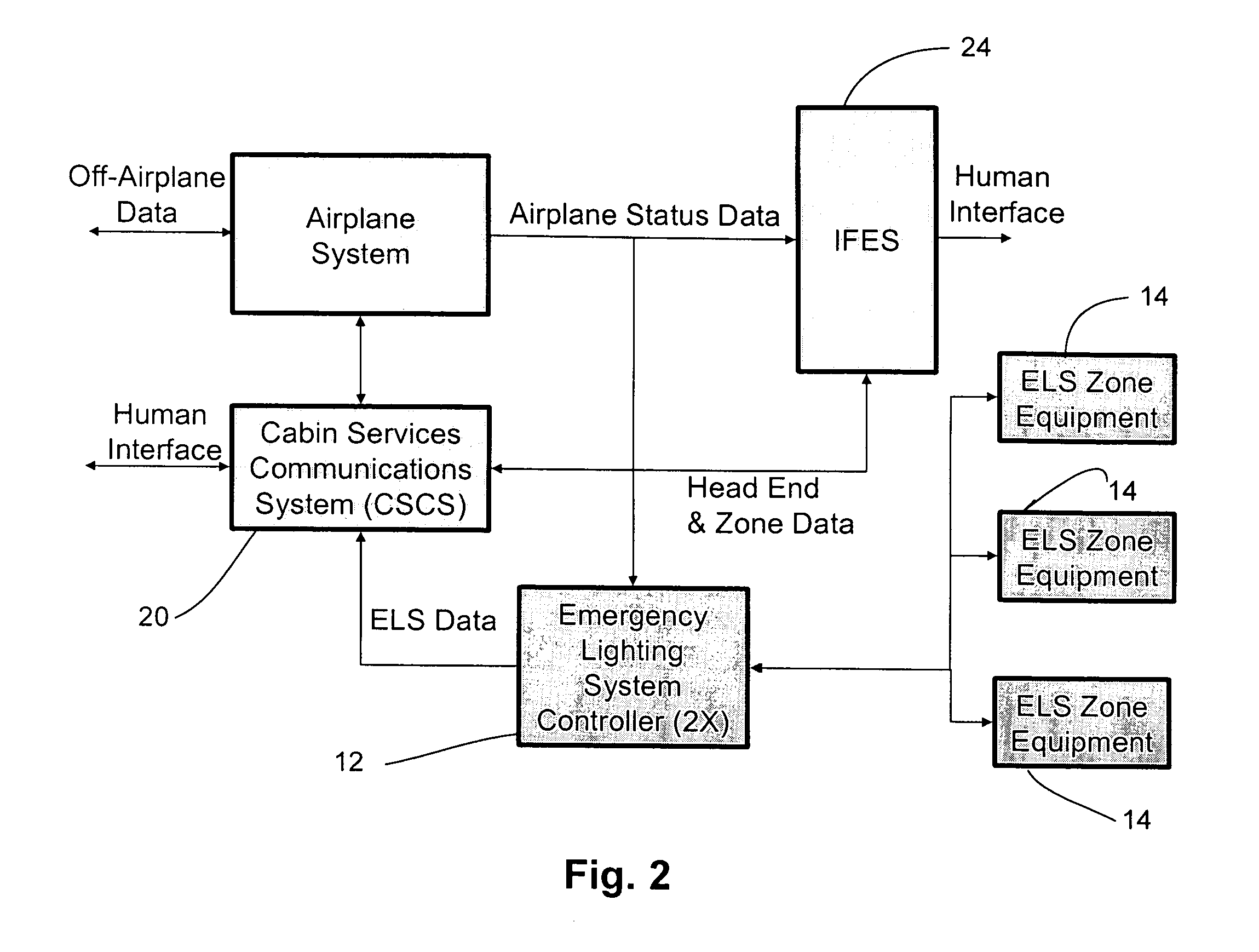
[0028]Referring now in detail to the drawings, wherein like reference numerals designate like or corresponding parts throughout the several views, and with reference to FIG. 1, there is shown a wireless communications system 10, such as a wireless emergency lighting system (WELS) for an aircraft. In the illustrated embodiment, the system 10 includes a WELS controller 12 in radio frequency (RF) wireless communication with a plurality of light assemblies 14, such as interior aircraft emergency lights, via one or more RF antennas 16 integrated into each light assembly 14. Any given light assembly 14 has a direct RF path to several other light assemblies. As is described more fully below, the controller 12 and light assemblies 14 can operate as a “virtual network” such that if the path between any two light assemblies becomes disrupted, alternate paths will be constructed under software control. The WELS 10 is in data communication, e.g., non-wireless communication, with a main communic...


PUM


Abstract

A wireless communications system suitable for use within an aircraft, such as a part of a wireless emergency lighting system (WELS) is provided. In an aircraft, EXIT signs are located throughout the interior of the aircraft, including the ceiling (general illumination), seats (floor proximity) and EXIT doors (locator / identifier). A wireless communications system uses an integrated lens antenna system that takes advantage of the quantity and location of emergency lights such that any given light will have a direct radio frequency (RF) path to several other lights. A virtual network can be created such that if the path between any two lights becomes disrupted, alternate paths will be constructed under software control.

Description

RELATED APPLICATION DATA[0001]This application claims the benefit of U.S. Provisional Application No. 60 / 544,445, filed Feb. 13, 2004, which is incorporated herein by reference in its entirety.TECHNICAL FIELD[0002]The invention herein described relates generally to wireless communications systems and, more particularly, to a wireless communications system for the interior of an aircraft.BACKGROUND OF THE INVENTION[0003]In many commercial settings, wireless networks have replaced the standard “hard wired” Ethernet network. For example, the Institute of Electrical and Electronic Engineers, the “IEEE”, 802.11 standard for wireless networking has been widely accepted. Manufacturers of a wide variety of products now offer many 802.11-compliant products for wireless networking. Wireless networks offer the advantage of accommodating moderately-sized numbers of users per radio frequency channel. As another example, the IEEE 802.15.4 standard defines the protocol and compatible interconnecti...

Claims


Application Information

Patent Timeline
Patent Type & Authority Patents(United States)
IPC IPC(8): G08B21/00H04B7/00
CPCH04B7/18506
Inventor MEYER, THOMAS J.
Owner GOODRICH LIGHTING SYST INC
Learn More