Supercharge Your Innovation With Domain-Expert AI Agents!

Control system of a robot cleaner

a robot cleaner and control system technology, applied in the direction of electric programme control, program control, instruments, etc., can solve the problems of inconvenient manual vacuum cleaners, inconvenient cleaning of manual vacuum cleaners, and inability to clean the divided local regions of conventional robot cleaners, so as to achieve the effect of cleaning local regions of a large area

Inactive Publication Date: 2008-03-11
SAMSUNG ELECTRONICS CO LTD
View PDF11 Cites 33 Cited by
  • Summary
  • Abstract
  • Description
  • Claims
  • Application Information

AI Technical Summary

Benefits of technology

Enables efficient and autonomous cleaning of local regions within large areas by allowing the robot cleaner to move and clean based on received reference signals, reducing user inconvenience and improving cleaning precision.

Problems solved by technology

Thus, manual vacuum cleaners are inconvenient because a user must move through the region to be cleaned while holding the manual vacuum cleaner itself or the vacuum head.
Further, manual vacuum cleaners are also problematic because noise is generated due to an operation of a motor that generates suction force, and the user has to do the actual moving of the manual vacuum and the cleaning work.
However, when the area to be cleaned is large, it becomes necessary to divide the large area into smaller regions rather than assign the entire large area to the conventional robot cleaner.
That is, in a case where a particular region of the given large area contains dust or other particles of dirt, the conventional robot cleaner can only clean the divided local regions of the given large area.
Further, the user is inconvenienced when a large area has to be subdivided into smaller areas because the conventional robot cleaner requires the user to input data in order to set the regions, and because it is difficult to precisely set the region, the setting of the region is usually based on subjective estimate of the user.
Accordingly, the conventional robot cleaner presents a problem, as the conventional robot cleaner is not able to easily clean local regions of a given large area.

Method used


Image

  • Control system of a robot cleaner
  • Control system of a robot cleaner
  • Control system of a robot cleaner

Examples


Embodiment Construction

[0021]Reference will now be made in detail to the present preferred embodiments of the present invention, examples of which are illustrated in the accompanying drawings, wherein like reference numerals refer to like elements throughout.

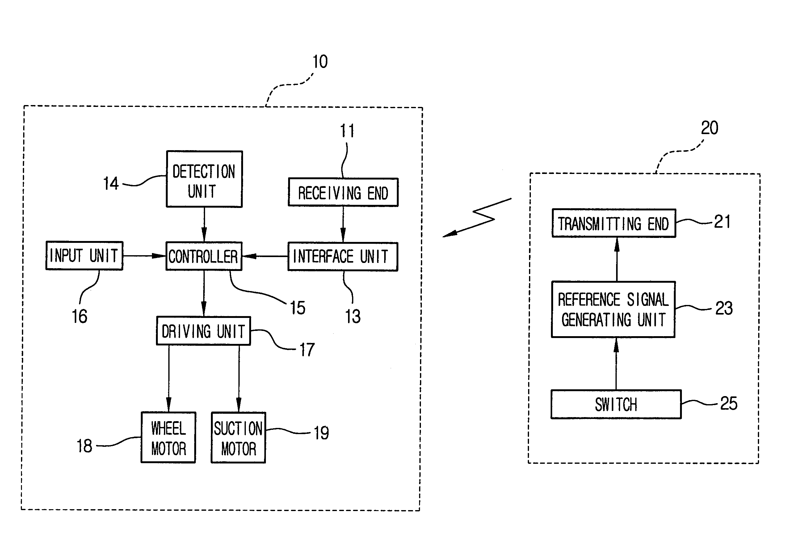
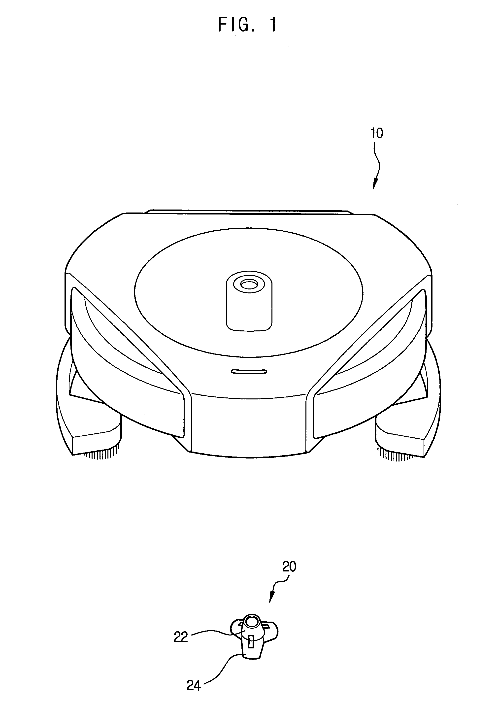
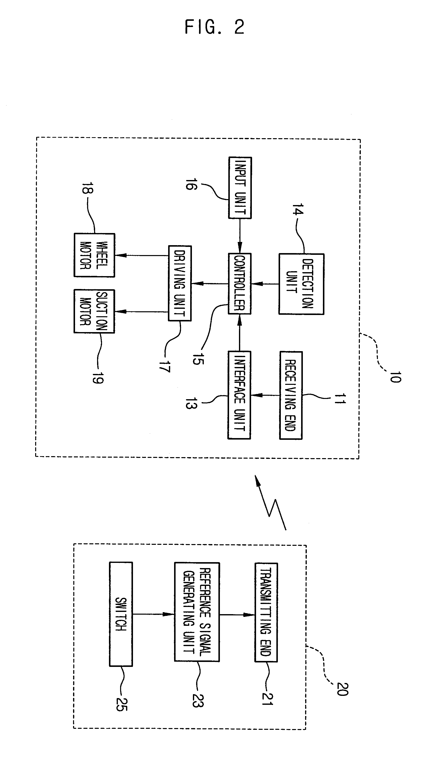
[0022]FIG. 1 is a perspective view of a control system of a robot cleaner, according to an aspect of the present invention. FIG. 2 is a block diagram of the control system of the robot cleaner. FIG. 3 is a perspective view to show a state in which the robot cleaner combined to the control system of FIG. 1 moves through a set region to be cleaned. FIG. 3 illustrates an example in which a cleaning unit 10 and a signal transmitting unit 20 are deployed in a local region that is part of a larger area to collect dust and / or other small particles of dirt.

[0023]The signal transmitting unit 20 wirelessly transmits reference signals to set a region to be cleaned D. The cleaning unit 10 receives the reference signal transmitted from the signal transmitting unit...


PUM


Abstract

A control system of a robot cleaner including a signal transmitting unit and a cleaning unit is provided. The signal transmitting unit wirelessly transmits reference signals, while the cleaning unit receives the reference signals from the signal transmitting unit and performs cleaning while moving through a region to be cleaned set in accordance to the received reference signals. Accordingly, the present invention causes the robot cleaner to be efficient in cleaning a local region of a given large area and provides for convenient use of the robot cleaner.

Description

CROSS-REFERENCE TO RELATED APPLICATIONS[0001]This application claims the benefit of Korean Application No. 2003-53175, filed Jul. 31, 2003, in the Korean Intellectual Property Office, the disclosure of which is incorporated herein by reference.BACKGROUND OF THE INVENTION[0002]1. Field of the Invention[0003]The present invention relates to a control system of a robot cleaner, which performs cleaning while autonomously moving through a region to be cleaned.[0004]2. Description of the Related Art[0005]A manual vacuum cleaner sucks up dust and other small particles of dirt, and collects the dust and particles of dirt in an internal container while being moved by a user through a region to be cleaned. According to a manual vacuum cleaner with separate components of a cleaner body and a vacuum head connected to each other by a flexible hose, the cleaner body is drawn to a desired position when a user moves while gripping the vacuum head. Thus, manual vacuum cleaners are inconvenient becau...

Claims


Application Information

Patent Timeline
Patent Type & Authority Patents(United States)
IPC IPC(8): G06F19/00A47L9/28G05D1/02
CPCG05D1/0234G05D1/0242G05D2201/0215A47L2201/04A47L9/28
Inventor ANN, SUNG JIN
Owner SAMSUNG ELECTRONICS CO LTD
Features
  • R&D
  • Intellectual Property
  • Life Sciences
  • Materials
  • Tech Scout
  • Unparalleled Data Quality
  • Higher Quality Content
  • 60% Fewer Hallucinations
Learn More