Electric plug comprising a plug housing and at least two integrated plug-in contacts with an ejection mechanism

a plug housing and plug-in contact technology, applied in the direction of coupling device connection, non-rotary current collector, engagement/disengagement of coupling parts, etc., can solve the problems of direct actuation of the plug and the inability to eject the plug in a quick and abrupt manner, so as to reduce the stress and exceed the maximum possible radius of action

Inactive Publication Date: 2008-03-18
MIELE & CO KG
View PDF12 Cites 14 Cited by
  • Summary
  • Abstract
  • Description
  • Claims
  • Application Information

AI Technical Summary

Benefits of technology

[0006]An object of the present invention is to improve an electric plug having a self-triggering ejection mechanism in such a way that the self-triggering ejection mechanism does not have to be actuated directly at the plug housing, the intention being to improve the ejection effect of the ejection means.
[0008]Another particular advantage that can be achieved with the present invention is that the ejection mechanism can be actuated from a position remote from the plug, using the cable. The advantage of this is that when using longer cables, as in the case of vacuum cleaners, ejection of the plug may be accomplished via the vacuum cleaner cable when the cable is in an extended condition. To this end, the actuation for the automatic triggering of the ejection mechanism is accomplished by pulling on the cable itself, the applied pulling force then acting on a strain relief device which is provided for the cable in the plug housing and which, in turn, cooperates with triggering means for actuating the push-out means which is biased by the spring. Thus, in particular, the pulling force is transmitted to the strain relief device via the cable sheath, without causing damage to the cable itself.
[0009]The automatic ejection mechanism reduces stress on the outlet and the strain relief device of the cable in the event of improper use, which occurs frequently in everyday life, such as removing the plug from the outlet by pulling on the cable, exceeding the maximum possible radius of action by pulling on the appliance.
[0010]The stress exerted on the outlet and the cable when tripping over the cable is also reduced by ejection of the plug. Ejection is possible not only by pulling lengthwise on the cable, but can also be accomplished by pulling in a transverse direction, as occurs frequently with outlets located in the area of a door.
[0013]In an advantageous refinement, a plate-like element is formed on the end of the plunger, said plate-like element pressing flat against a contact surface in the outlet during the ejection process. Thus, the force is applied to the surface of the outlet in a uniformly distributed manner, avoiding damaging point loads.

Problems solved by technology

It is considered a disadvantage of the first-mentioned ejection mechanism that it can only be actuated directly at the plug.
In the second-mentioned design approach, it is considered a disadvantage that biasing of the ejection mechanism is via the housing itself, and that the plug cannot be ejected in a quick and abrupt manner due to the frictional losses occurring during the movement of the ejection means in the connecting link guide.

Method used


Image

  • Electric plug comprising a plug housing and at least two integrated plug-in contacts with an ejection mechanism
  • Electric plug comprising a plug housing and at least two integrated plug-in contacts with an ejection mechanism

Examples


Embodiment Construction

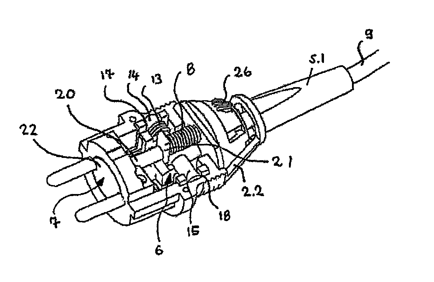
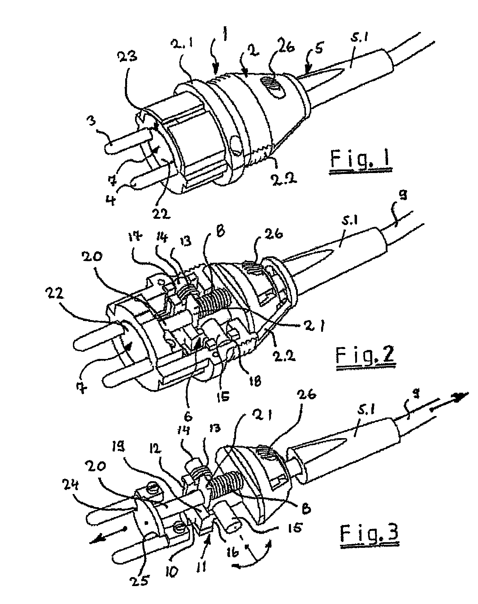
[0019]FIG. 1 shows, in a perspective view, an electric plug 1 having a plug housing 2 and at least two integrated plug-in contacts 3 and 4 to be inserted into corresponding female receptacles (not shown) of an outlet. Plug housing 2 is substantially composed of two housing shells 2.1 and 2.2 enclosing the cable entry 5 on the one hand, and also an ejection mechanism 6 including push-out means 7. A push-out means 7 cooperates with a spring 8 (shown more clearly in FIGS. 2 and 3) in such a way that spring 8 is biased when plug 1 is in the plugged-in state. When actuating ejection mechanism 6, plug 1 is automatically removed from the outlet (not specifically shown) by means of push-out means 7. To this end, spring 8 is released, so that push-out means 7 moves out in the direction of the arrow shown.

[0020]In accordance with the present invention, the actuation for the automatic triggering of ejection mechanism 6 is accomplished by pulling on cable 9, the pulling force (also indicated by...


PUM


Abstract

An electric plug includes a plug housing, at least two incorporated plug-in contacts that are to be inserted into corresponding jacks of an outlet, and a cable feeder. A manually actuated ejection mechanism encompassing a push-out device is disposed in the plug housing. The push-out device cooperates with a spring in such a way that the spring is biased in the plugged-in state of the plug in order to allow the plug to be automatically removed from the outlet by means of the push-out device when the ejection mechanism is actuated. In order to actuate the ejection mechanism, the same is automatically triggered by pulling on the cable, the tensile force being effective on a strain relief device for the cable, which is located in the plug housing and cooperates with triggering device for actuating the spring-biased push-out device.

Description

CROSS REFERENCE TO PRIOR APPLICATIONS[0001]This application is a U.S. National Phase of International Patent Application No. PCT / EP2005 / 001613, filed Feb. 17, 2005, which claims priority to German Patent Application No. DE 10 2004 009 403.9, filed Feb. 24, 2004, the entire disclosure of which is incorporated by reference herein. The International Application was published in German on Sep. 1, 2005 as WO 2005 / 081367 A1.FIELD OF THE INVENTION[0002]The present invention relates to an electric plug including a plug housing and at least two integrated plug-in contacts to be inserted into corresponding female receptacles of an outlet, and a cable entry, a manually actuated ejection mechanism having push-out means being disposed in the plug housing, and the push-out means cooperating with a spring in such a way that the spring is biased when the plug is in the plugged-in state, so that the plug is automatically removed from the outlet by means of the push-out means when the ejection mechan...

Claims


Application Information

Patent Timeline
Patent Type & Authority Patents(United States)
IPC IPC(8): H01R13/62H01R13/635
CPCH01R13/635H01R24/28H01R2103/00
Inventor BULLER, KAISCHMEDT, ANDREASWEGENER, DIRK
Owner MIELE & CO KG
Why Eureka
Try Eureka