Supercharge Your Innovation With Domain-Expert AI Agents!

Compact fuel cell stack structure

a fuel cell and stack structure technology, applied in the field of fuel cells, can solve the problems of difficult tie rod tightening to impart the desired compressive force, and the assembly of fuel cells requires a significant amount of compressive force to squeeze fuel

Inactive Publication Date: 2008-03-18
GM GLOBAL TECH OPERATIONS LLC
View PDF30 Cites 3 Cited by
  • Summary
  • Abstract
  • Description
  • Claims
  • Application Information

AI Technical Summary

Benefits of technology

[0011]Preferably, the first and second ends of the side wall are secured to the first and second end plates with mechanical fasteners. Even more preferably, the side walls include a slot for receiving the mechanical fastener.
[0012]In a second preferred embodiment, an electrochemical fuel cell stack comprises a plurality of fuel cells arranged in a stacked configuration to form a fuel cell assembly having opposite first and second ends and a length therebetween. First and second end plates are disposed on the respective first and second ends and impart a compressive force on the fuel cell assembly. A side wall is attached to the first and second end plates. The side wall has opposite first and second ends that are attached to the respective first and second end plates. The side wall encloses a portion of the fuel cell assembly between the first and second end plates and provides a protective enclosure for the fuel cell assembly. Preferably, the side wall is attached to the end plates such that the end plates are held in a spaced relation to impart a compressive force on the fuel cell assembly.
[0013]Preferably, the side wall provides shielding against electromagnetic interference with the fuel cell assembly. Even more preferably, the one side wall is electrically grounded.

Problems solved by technology

The fuel cell assembly requires a significant amount of compressive force to squeeze the fuel cells of the stack together.
When the stack structure utilizes tie rods distributed around a periphery of the end plate to impart a compressive force on the fuel cell assembly, the proper tightening of the tie rods to impart the desired compressive force can be difficult.

Method used


Image

  • Compact fuel cell stack structure
  • Compact fuel cell stack structure
  • Compact fuel cell stack structure

Examples


Embodiment Construction

[0035]The following description of the preferred embodiment(s) is merely exemplary in nature and is in no way intended to limit the invention, its application, or uses.

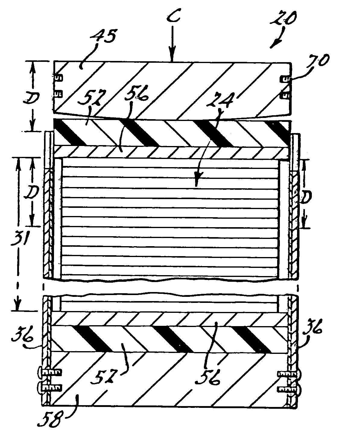
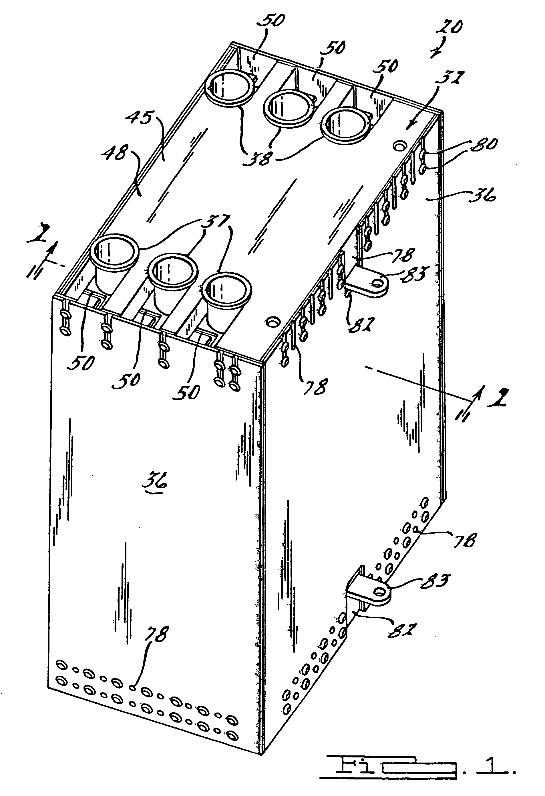
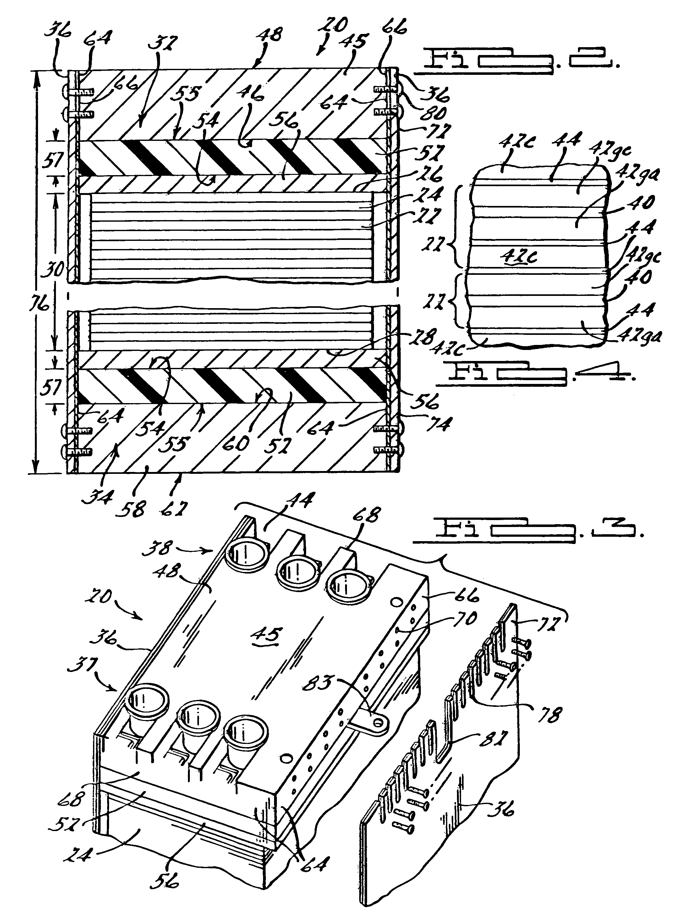
[0036]Referring to FIGS. 1 and 2, there is shown an electrochemical fuel cell stack 20 in accordance with a preferred embodiment of the present invention. The fuel cell stack 20 includes a plurality of fuel cells 22 arranged in a stacked configuration to form a fuel cell assembly 24 having opposite upper and lower ends 26, 28 with a compressed length 30 and an uncompressed length 31, is shown in FIG. 10A, therebetween. The fuel cell assembly 24 is interposed between upper and lower end assemblies 32, 34. The upper and lower end assemblies 32, 34 are held in a fixed spaced relation by a side wall. In the presently preferred embodiment, the side wall includes at least one side plate 36. The side plates 36 hold the upper and lower end assemblies 32, 34 in a spaced relation so that the upper and lower end assemblies 32, 3...


PUM

PropertyMeasurementUnit
areaaaaaaaaaaa
thicknessaaaaaaaaaa
thicknessaaaaaaaaaa

Abstract

An electro-chemical fuel cell stack having a plurality of fuel cells arranged in a stacked configuration to form a fuel cell assembly. The fuel cell assembly has opposite first and second ends with a length therebetween. First and second end plates are disposed on the respective first and second ends of the fuel cell assembly. The stack has at least one side plate with opposite first and second ends that are attached to the respective first and second end plates. The side plate holds the first and second end plates in a spaced relation so that the first and second end plates impart a compressive force on the fuel cell assembly. The side plate also encloses the fuel cell assembly between the first and second end plates and provides a protective enclosure for the fuel cell assembly.

Description

FIELD OF THE INVENTION[0001]The present invention relates to fuel cells and, more particularly, to fuel cells arranged in a stack and held in compression.BACKGROUND OF THE INVENTION[0002]Fuel cell stacks typically comprise a plurality of fuel cells stacked one upon the other and held in compression with respect to each other. The plurality of stacked fuel cells form a fuel cell assembly which is compressed to hold the plurality of fuel cells in a compressive relation. Typically, each fuel cell comprises an anode layer, a cathode layer, and an electrolyte interposed between the anode layer and the cathode layer. The fuel cell assembly requires a significant amount of compressive force to squeeze the fuel cells of the stack together. The need for the compressive force comes about from the internal gas pressure of the reactants within the fuel cells plus the need to maintain good electrical contact between the internal components of the cells. Generally, the per area unit force is abou...

Claims


Application Information

Patent Timeline
Patent Type & Authority Patents(United States)
IPC IPC(8): H01M8/02H01M8/24H01M2/02H01M8/10
CPCH01M8/2475H01M8/248H01M2008/1095Y02E60/50
Inventor ROCK, JEFFREY A
Owner GM GLOBAL TECH OPERATIONS LLC
Features
  • R&D
  • Intellectual Property
  • Life Sciences
  • Materials
  • Tech Scout
  • Unparalleled Data Quality
  • Higher Quality Content
  • 60% Fewer Hallucinations
Learn More