Bendable bottom member for bed

a bed and bottom member technology, applied in the field of bed bottom members, can solve the problems of lowering the stability of the entire form, affecting the comfort of users, and displacing the patient lying on the bed mattress by the disadvantageous pressure felt on the abdomen, and achieve the effect of high degree of freedom

Inactive Publication Date: 2008-03-25
PARAMOUNT BED CO LTD
View PDF10 Cites 4 Cited by
  • Summary
  • Abstract
  • Description
  • Claims
  • Application Information

AI Technical Summary

Benefits of technology

[0029]Because of the above, in the bendable bottom member of this invention, it is not necessary to let the length of the most extended curved state accurately agree with the actual distance between the end of the back bottom member and the waist bottom member, and it is only required that at least the length of the most shortened flat state is kept smaller than the actual distance between the end of the back bottom member and the waist bottom member. So, a high degree of freedom is assured in design to avoid mechanical inconsistency.

Problems solved by technology

However, for example, if the bed is designed to allow the back region and the waist region to be bent by simple pivotal rotation, the mattress supported on the bottom is compressed by the bent back bottom member and waist bottom member, and the bed user such as a patient lying on the mattress is displeased by the pressure felt on the abdomen disadvantageously.
However, the constitution that adjacent plates are engaged with each other using connecting shafts and slots to form a curve in any direction by simple pivotal rotation at the engagement, as adopted in the above extendable and bendable portion, has the following problems.
The extendable and bendable portion has a high degree of freedom in the entire form since the number of bending points is as many as four, but since it can be bent in any direction at the respective bending points, the respective plates do not always move evenly in the transfer from the shortened flat state to the extended curved state or in the transfer reverse to it, and any local load lowers the corresponding plate downward to change the entire form, lowering the stability of the entire form.
So, in the extended state, the extendable and bendable portion is not always curved at a proper angle, and it can happen that the bed user feels instability.

Method used


Image

  • Bendable bottom member for bed
  • Bendable bottom member for bed
  • Bendable bottom member for bed

Examples


Embodiment Construction

[0042]A preferred embodiment of this invention is described below in reference to the drawings.

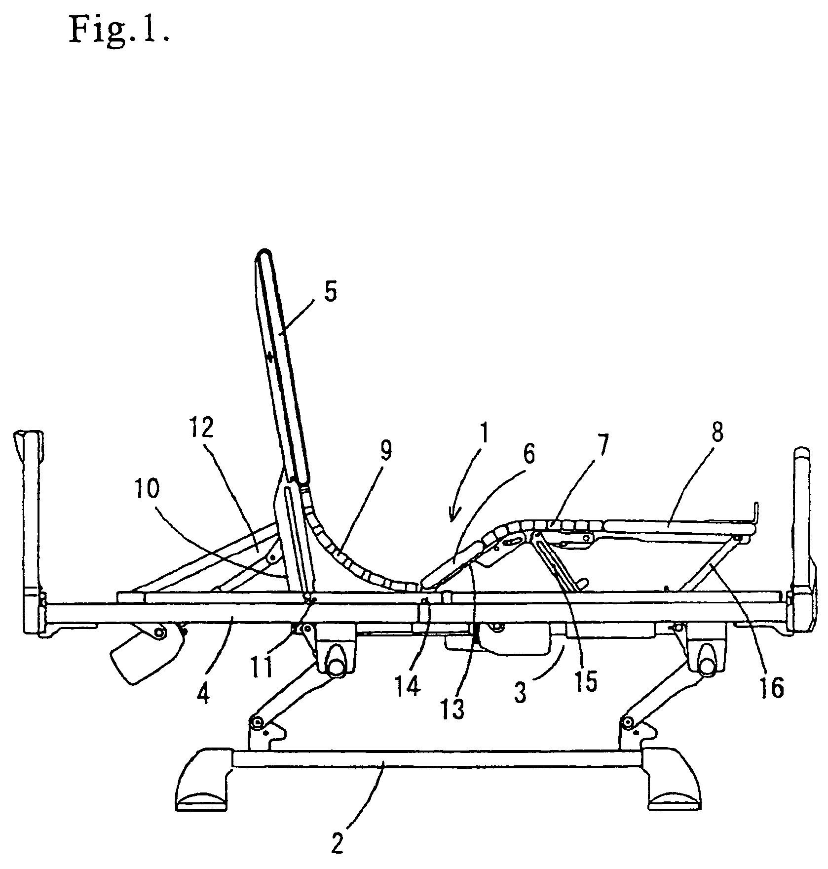
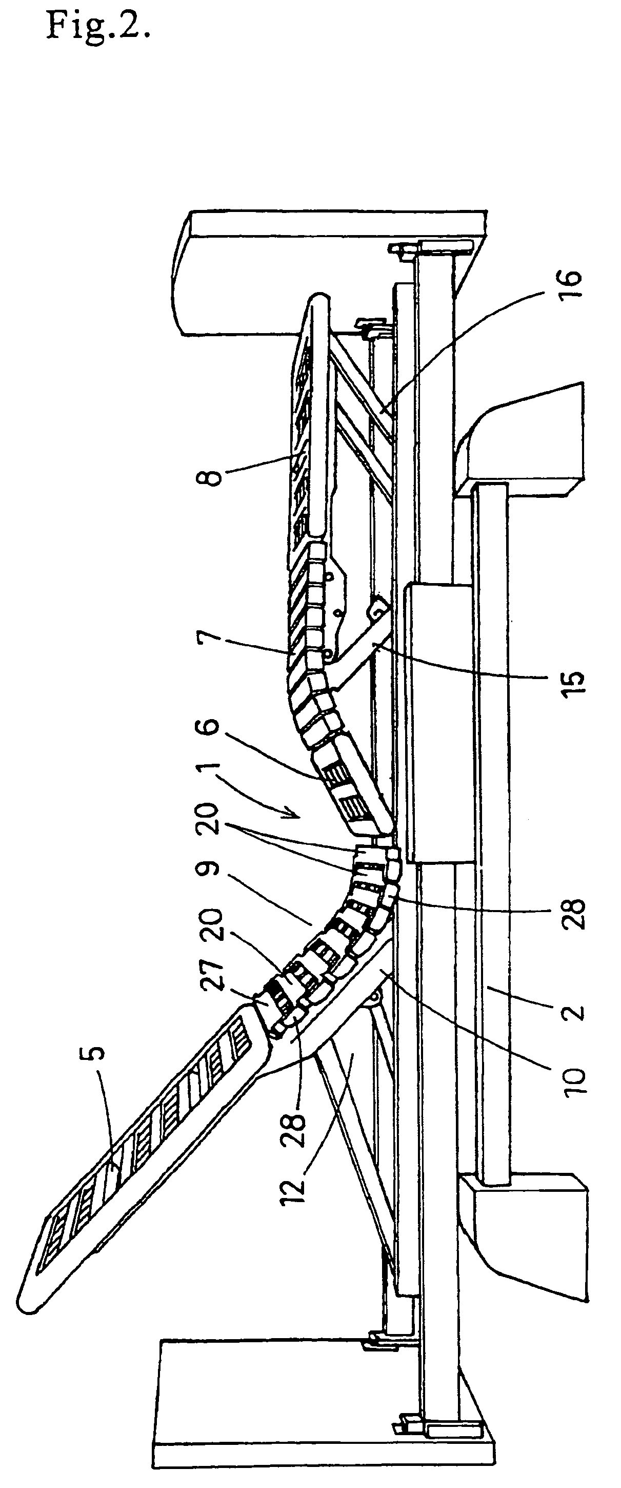
[0043]At first, in FIGS. 1 through 3, symbol 1 generally denotes a bottom which is curvewise liftably supported on a deck support frame 4 liftably supported by a proper lifting mechanism 3 above a base frame 2.

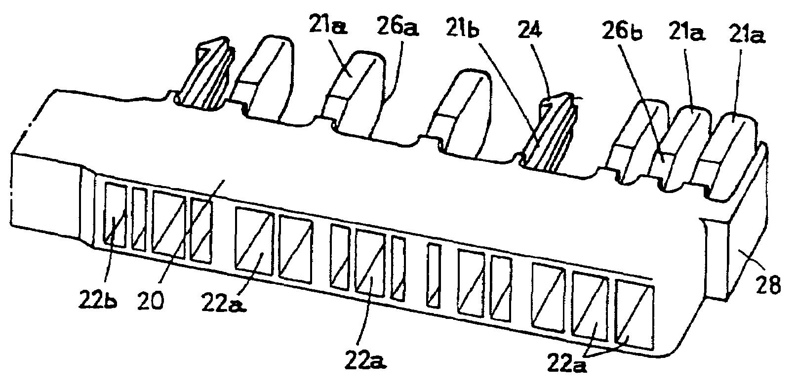
[0044]The bottom 1 consists of a back bottom member 5, a waist bottom member 6, a knee bottom member 7, a leg bottom member 8 and a bendable bottom member 9 of this invention disposed between the back bottom member 5 and the waist bottom member 6.

[0045]The back bottom member 5 is supported by a pivotally rotating arm 10 and pivotally rotated around a fulcrum 11, to be lifted by a back lifting mechanism 12, and the waist bottom member 6 is supported by a pivotally rotating arm 13 and pivotally rotated around a fulcrum 14, to be lifted. On the other hand, the knee bottom member 7 connected between the waist bottom member 6 and the leg bottom member 8 is a bendable bottom member constit...


PUM


Abstract

A bed having a bendable portion between a back region and waist region and / or a waist region and leg region. The bendable portion is formed of side by side bars disposed generally perpendicular to the longitudinal axis of the bed and bendably connected together to allow the whole extent of the connecting bars to be shortened, extended, and curved. The bars are connected by protrusions on one bar extending into recesses of an adjacent bar. Side by side bars can be adjusted in their intervals and can be rotated in one direction up to a predetermined angle.

Description

CROSS REFERENCE TO A RELATED APPLICATIONS[0001]This is a continuation patent application of application Ser. No. 10 / 005,129 filed Dec. 7, 2001, now abandoned.FIELD OF THE INVENTION[0002]This invention relates to a bendable bottom member for a bed capable of being lifted in the back bottom member, leg bottom member, etc., to be used for the bendable portion between the back region and the waist region and / or between the waist region and the leg region.BACKGROUND OF THE INVENTION[0003]A bed capable of being lifted in the back bottom member, leg bottom member, etc. has a basic constitution in which the deck is divided into a plurality of regions, say, back region, waist region, leg region and foot region and in which the respective regions are connected bendably with each other or some of them are supported pivotally rotatably on a frame supporting the bottom, so that they can be bent.[0004]However, for example, if the bed is designed to allow the back region and the waist region to be...

Claims


Application Information

Patent Timeline
Patent Type & Authority Patents(United States)
IPC IPC(8): A47B7/02A47C19/00A47C20/04A47C23/00A47C23/06A47C31/12A61G7/00
CPCA47C20/04A47C23/005A47C23/06A47C31/123
Inventor TAKEUCHI, HIROSHI
Owner PARAMOUNT BED CO LTD
Why Eureka
Try Eureka