Beverage bottling plant for filling bottles with a liquid beverage having a filling machine for filling bottles with a liquid beverage

a technology for filling machines and beverage bottling plants, which is applied in the direction of filling using counterpressure, packaging under special atmospheric conditions, packaging, etc., can solve the problems of increased risk of contamination of goods being bottled, high risk, and inability to fully rule out a more serious contamination of liquids

Active Publication Date: 2008-03-25
KHS GMBH
View PDF15 Cites 20 Cited by
  • Summary
  • Abstract
  • Description
  • Claims
  • Application Information

AI Technical Summary

Benefits of technology

[0012]The object of this invention is to substantially reduce or essentially eliminate the disadvantages described above. For this purpose the invention teaches a filling machine in which a return gas tube ends directly in a separate return gas duct, whereby said return gas duct is connected with the storage reservoir through an opening that has a small cross section area, and the return gas duct and storage reservoir are connected with a common source of negative pressure or vacuum and are at essentially the same pressure.

Problems solved by technology

In configurations of this type, in which ambient air, or at least the flushing gas that has been in contact with the container comes directly into contact with the liquid being bottled, there is necessarily an increased risk of contamination of the goods being bottled.
This risk is particularly high if the return gas and the goods being bottled come into contact with each other over large areas.
In this configuration, of course, the return gas initially comes into contact only with the volume of liquid being bottled that is located in the filling mechanism itself, as a result of which the risk of contamination is reduced, although it is impossible to fully rule out a more serious contamination of the liquid being bottled, because the return gas from any filling mechanism can travel through a large-diameter passage opening into the ring bowl.
Because of the shuttle valve that is provided and the different pressure settings, however, such a device is mechanically complex and expensive to manufacture.

Method used


Image

  • Beverage bottling plant for filling bottles with a liquid beverage having a filling machine for filling bottles with a liquid beverage
  • Beverage bottling plant for filling bottles with a liquid beverage having a filling machine for filling bottles with a liquid beverage
  • Beverage bottling plant for filling bottles with a liquid beverage having a filling machine for filling bottles with a liquid beverage

Examples


Embodiment Construction

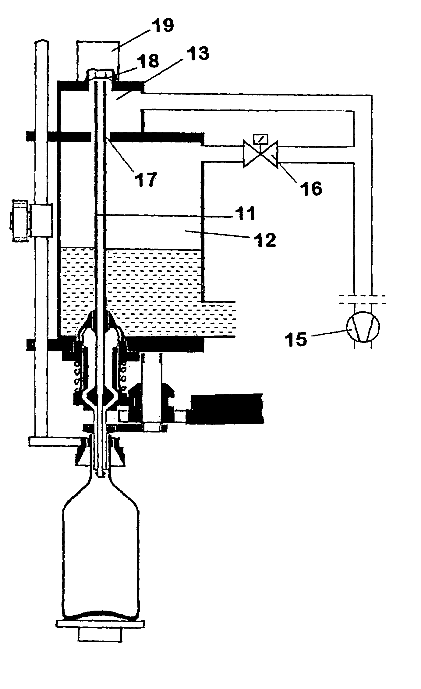
[0020]Developments, advantages and potential applications of the invention are described below with reference to exemplary embodiments and to the accompanying drawings. All the features described and / or illustrated, individually or in any desired combination, are the object of the invention regardless of their combination or placement in the claims or the references to other claims. The text of the claims is also integrated by reference into the description.

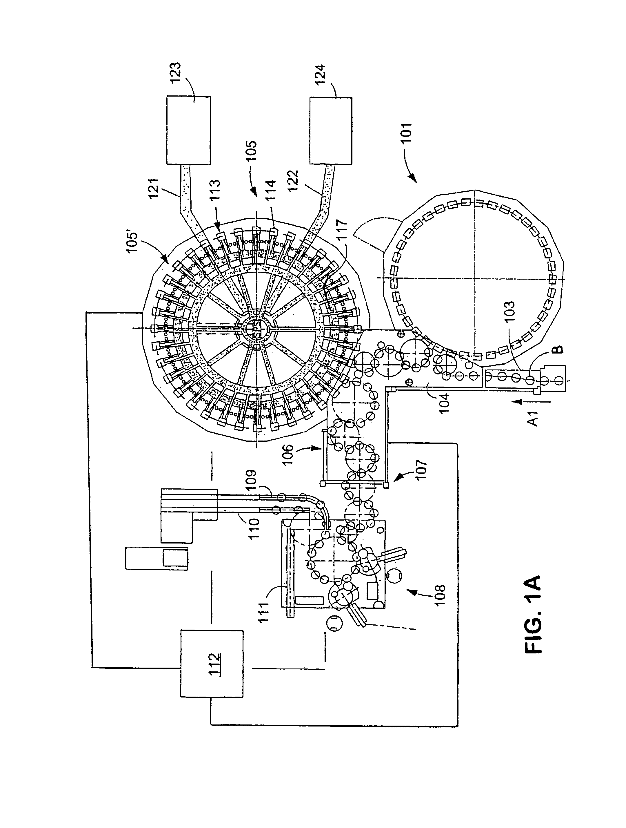
[0021]FIG. 1A shows schematically the main components of one possible embodiment example of a system for filling containers, specifically, a beverage bottling plant for filling bottles B with at least one liquid beverage, in accordance with at least one possible embodiment, in which system or plant could possibly be utilized at least one aspect, or several aspects, of the embodiments disclosed herein.

[0022]FIG. 1A shows a rinsing arrangement or rinsing station 101, to which the containers, namely bottles B, are fed in the directi...


PUM


Abstract

Beverage bottling plant for filling bottles with a liquid beverage having a filling machine for filling bottles and other beverage containers with a liquid beverage. The filling machine having a gas tube being configured and disposed to permit evacuation of gas from a beverage bottle to a chamber of a return gas duct without the gas contacting liquid beverage material in a beverage storage reservoir to essentially prevent contamination of the liquid beverage material in said beverage storage reservoir by the gas being evacuated from the beverage bottle.

Description

BACKGROUND[0001]1. Technical Field[0002]The present application relates to a beverage bottling plant for filling bottles with a liquid beverage having a filling machine as described herein below.[0003]2. Background Information[0004]A beverage bottling plant for filling bottles with a liquid beverage filling material can possibly comprise a beverage filling machine with a plurality of beverage filling positions, each beverage filling position having a beverage filling device for filling bottles with liquid beverage filling material. The filling devices may have an apparatus designed to introduce a predetermined volume of liquid beverage filling material into the interior of bottles to a substantially predetermined level of liquid beverage filling material. The apparatus designed to introduce a predetermined flow of liquid beverage filling material further comprises an apparatus that is designed to terminate the filling of the beverage bottles upon the liquid beverage filling material...

Claims


Application Information

Patent Timeline
Patent Type & Authority Patents(United States)
IPC IPC(8): B65B31/00B67C3/06B67C3/26
CPCB67C3/06B67C3/2614B67C2003/2602
Inventor SCHMOLL, WOLFGANG
Owner KHS GMBH
Why Eureka
Try Eureka