Shower head

a shower head and shower head technology, applied in the field of shower head, can solve the problems of increasing the cost of fabrication and assembly, inconvenience for users, and the conventional shower head is not operated smoothly, and achieves the effect of reducing the cost of fabrication, facilitating operation, and constant water flow ra

Inactive Publication Date: 2008-03-25
SHONG I COPPER +1
View PDF6 Cites 91 Cited by
  • Summary
  • Abstract
  • Description
  • Claims
  • Application Information

AI Technical Summary

Benefits of technology

[0006]The primary objective of the present invention is to provide a shower head, wherein the connecting disk is moved toward the main body by rotation of the adjusting bolt so that the O-ring is moved upward with the connecting disk and closely urged on the inner wall of the main body, thereby forming a closely sealing effect between the connecting disk and the inner wall of the main body.
[0008]A further objective of the present invention is to provide a shower head, wherein the user only needs to rotate the adjusting bolt to move the connecting disk and the water outlet faceplate toward the main body, thereby facilitating the user adjusting the tension between the water outlet faceplate and the main body.
[0009]A further objective of the present invention is to provide a shower head, wherein the connecting disk and the water outlet faceplate are removed from the main body by unscrewing the adjusting bolt, thereby facilitating the user cleaning the water outlet holes of the water outlet faceplate.
[0010]A further objective of the present invention is to provide a shower head, wherein the water is directly injected outward from the water outlet holes of the water outlet faceplate for use with a user, so that the shower head is operated smoothly and has a constant water flow rate.
[0011]A further objective of the present invention is to provide a shower head, wherein the connecting disk is integrally formed with the locking sleeve, thereby decreasing costs of fabrication, and thereby simplifying the process of assembly.

Problems solved by technology

However, the conventional shower head has a complicated construction, thereby increasing costs of fabrication and assembly.
Further, the spray plate 10 is integrally formed with the upper wall 8 so that the spray plate 10 cannot be removed from the upper wall 8, thereby causing inconvenience to a user when cleaning the water outlet holes of the spray plate 10.
Further, the conventional shower head is not operated smoothly and does not have a constant water flow rate.

Method used


Image

  • Shower head
  • Shower head
  • Shower head

Examples


Embodiment Construction

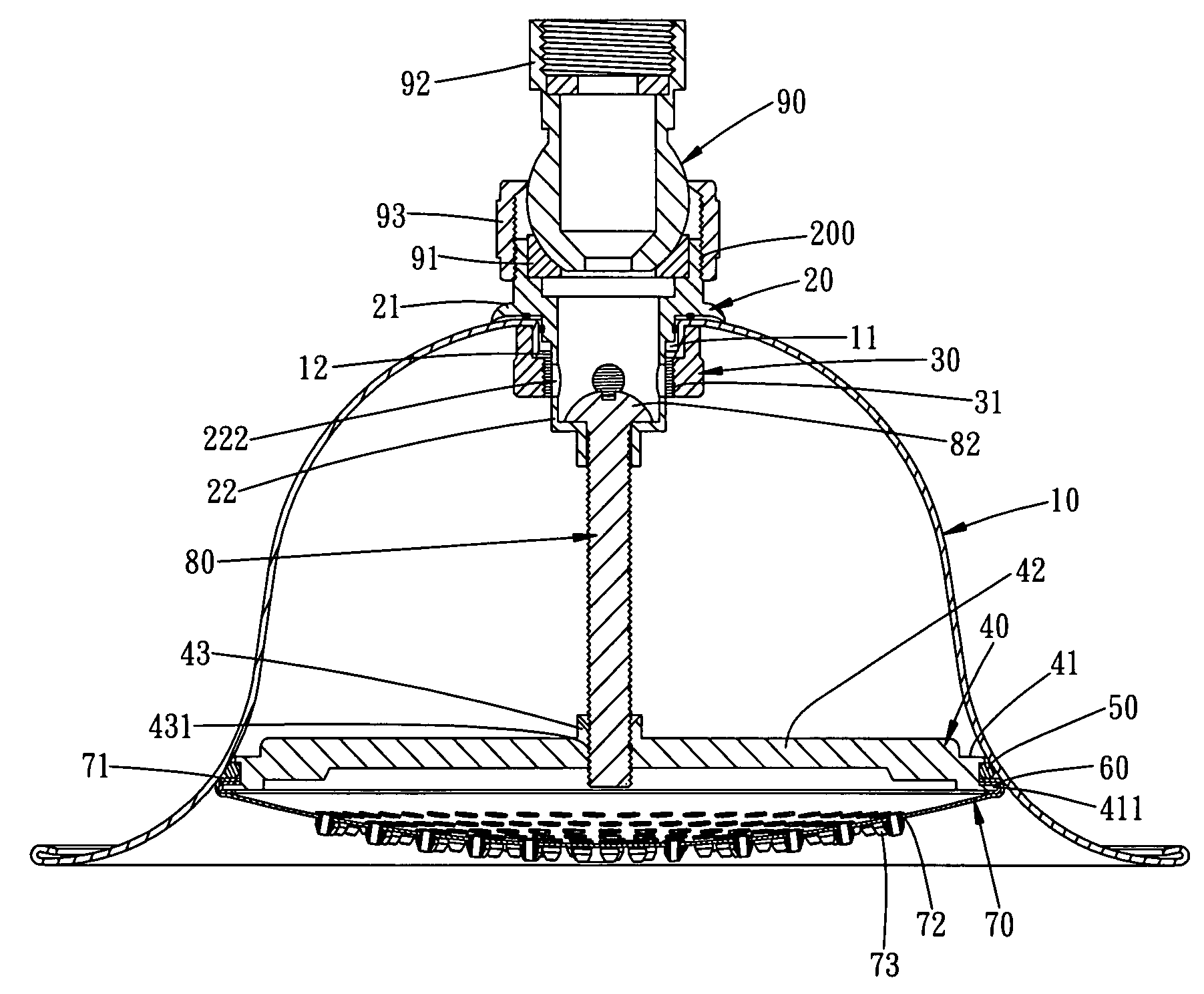
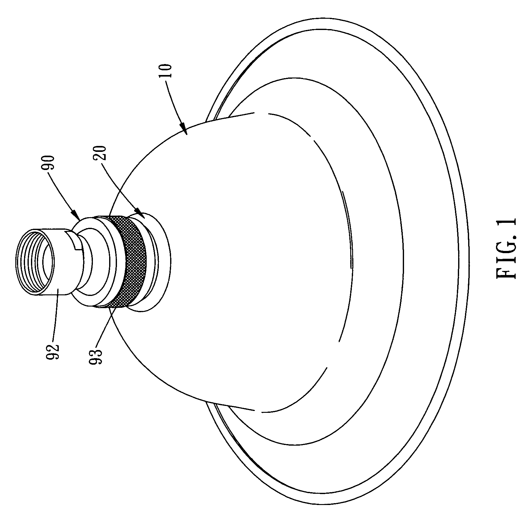
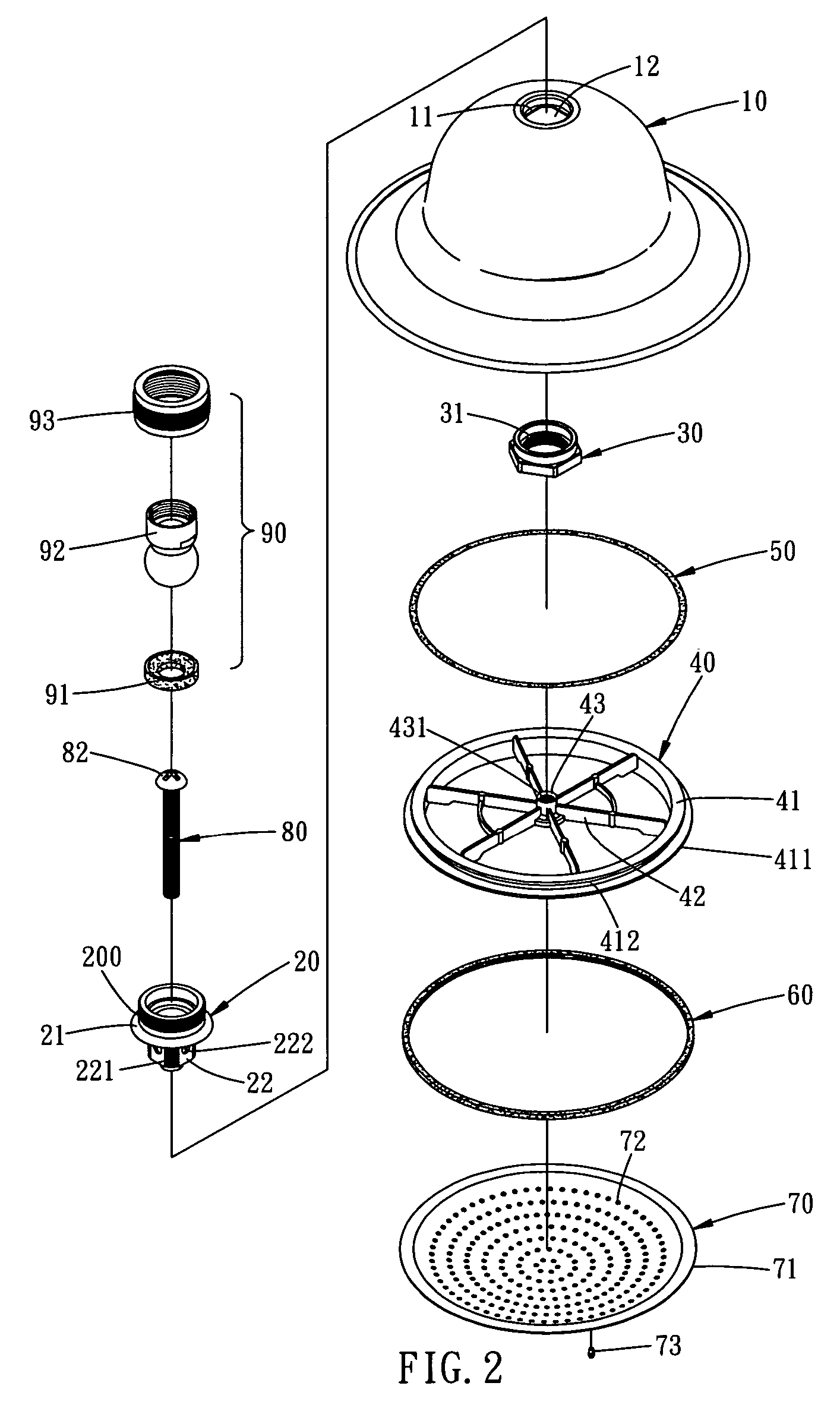
[0018]Referring to the drawings and initially to FIGS. 1-4, a shower head in accordance with the preferred embodiment of the present invention comprises a main body 10, a mounting seat 20, a locking nut 30, a connecting disk 40, an O-ring 50, a gasket 60, a water outlet faceplate 70, an adjusting bolt 80, and a connector unit 90.

[0019]The main body 10 has a bell shape and has a closed upper portion and an open lower portion. The upper portion of the main body 10 is formed with a circular recess 11 having a bottom face formed with a substantially square chamfered positioning hole 12.

[0020]The mounting seat 20 is secured on the upper portion of the main body 10 and has an upper portion protruding outward from the main body 10, a lower end formed with a substantially square chamfered mounting portion 22 secured in the positioning hole 12 of the main body 10 and a mediate portion formed with an outward extended substantially arc-shaped resting flange 21 rested on the upper portion of th...


PUM


Abstract

A shower head includes a main body, a mounting seat, a locking nut, a connecting disk, an O-ring, a gasket, a water outlet faceplate, an adjusting bolt, and a connector unit. Thus, the connecting disk is moved toward the main body by rotation of the adjusting bolt so that the O-ring is moved upward with the connecting disk and closely urged on the inner wall of the main body, thereby forming a closely sealing effect between the connecting disk and the inner wall of the main body.

Description

BACKGROUND OF THE INVENTION[0001]1. Field of the Invention[0002]The present invention relates to a shower head, and more particularly to a shower head having a closely sealing effect.[0003]2. Description of the Related Art[0004]A conventional shower head in accordance with the prior art is disclosed in U.S. Pat. No. 6,241,166. However, the conventional shower head has a complicated construction, thereby increasing costs of fabrication and assembly. In addition, when the bolt 38 is rotated to pull the bush 42 and the upper wall 8 upward to press the sealing ring 16, the upper wall 8 is easily deformed to reduce its diameter, thereby forming a clearance between the upper wall 8 and the spray plate 10 so that the shower head easily produces leak. Further, the spray plate 10 is integrally formed with the upper wall 8 so that the spray plate 10 cannot be removed from the upper wall 8, thereby causing inconvenience to a user when cleaning the water outlet holes of the spray plate 10. Furt...

Claims


Application Information

Patent Timeline
Patent Type & Authority Patents(United States)
IPC IPC(8): B05B1/18B05B1/00B05B1/14
CPCB05B1/185B05B15/067B05B15/654
Inventor CHUNG, CHIN-TANG
Owner SHONG I COPPER
Why Eureka
Try Eureka