Hole plug

Inactive Publication Date: 2008-03-25
NIFCO INC
View PDF20 Cites 26 Cited by
  • Summary
  • Abstract
  • Description
  • Claims
  • Application Information

AI Technical Summary

Benefits of technology

[0014]According to the fourth aspect of the invention, the column integrally projects from the back surface of the head portion at an inside of a section defined by the uprising plates, and each of the supporting devices connects the column to each of the uprising plates. Thus, the inward bending force in the radial direction upon the insertion can be specifically received at the column through the supporting devices, and the stable engagement between the engaging step portions and the rim of the hole can be maintained.
[0015]According to the fifth aspect of the invention, each of the supporting devices is formed in a wavy plate, and the wavy plate is disposed such that the plate surface projects from the back surface of the head portion. Thus, it is possible to limit each of the uprising plates so as not to bend inwardly in the radial direction upon the insertion, while utilizing elasticity of the wavy plate to a certain extent. Accordingly, the insertion can be easily accomplished, and the stable engagement between the engaging step portions and the rim of the hole can be fully satisfied.
[0016]According to the sixth aspect of the invention, when the hole plug of the present invention is inserted into the hole, first, each of the guide portions is inserted into the hole. Following the guide portions, the foot portions, i.e. the uprising plates are smoothly guided into the hole. Thus, the insertion can be easily and properly done.
[0017]According to the seventh aspect of the invention, the cylindrical column integrally projects from the back surface of the head portion at an inside of a section defined by the uprising plates. The inner side surface of each of the guide portions is integrated with th

Problems solved by technology

However, in the case where the rim of the hole is held between the rim of the head portion and the engaging step portion at the end of each engaging claw with the above-mentioned hole plug, not only the rim of the head portion is bent, but also the engaging claw is easily bent (deforming in a direction that the engaging step portion moves away from the back surface of the head portion).
T

Method used


Image

  • Hole plug
  • Hole plug
  • Hole plug

Examples


Embodiment Construction

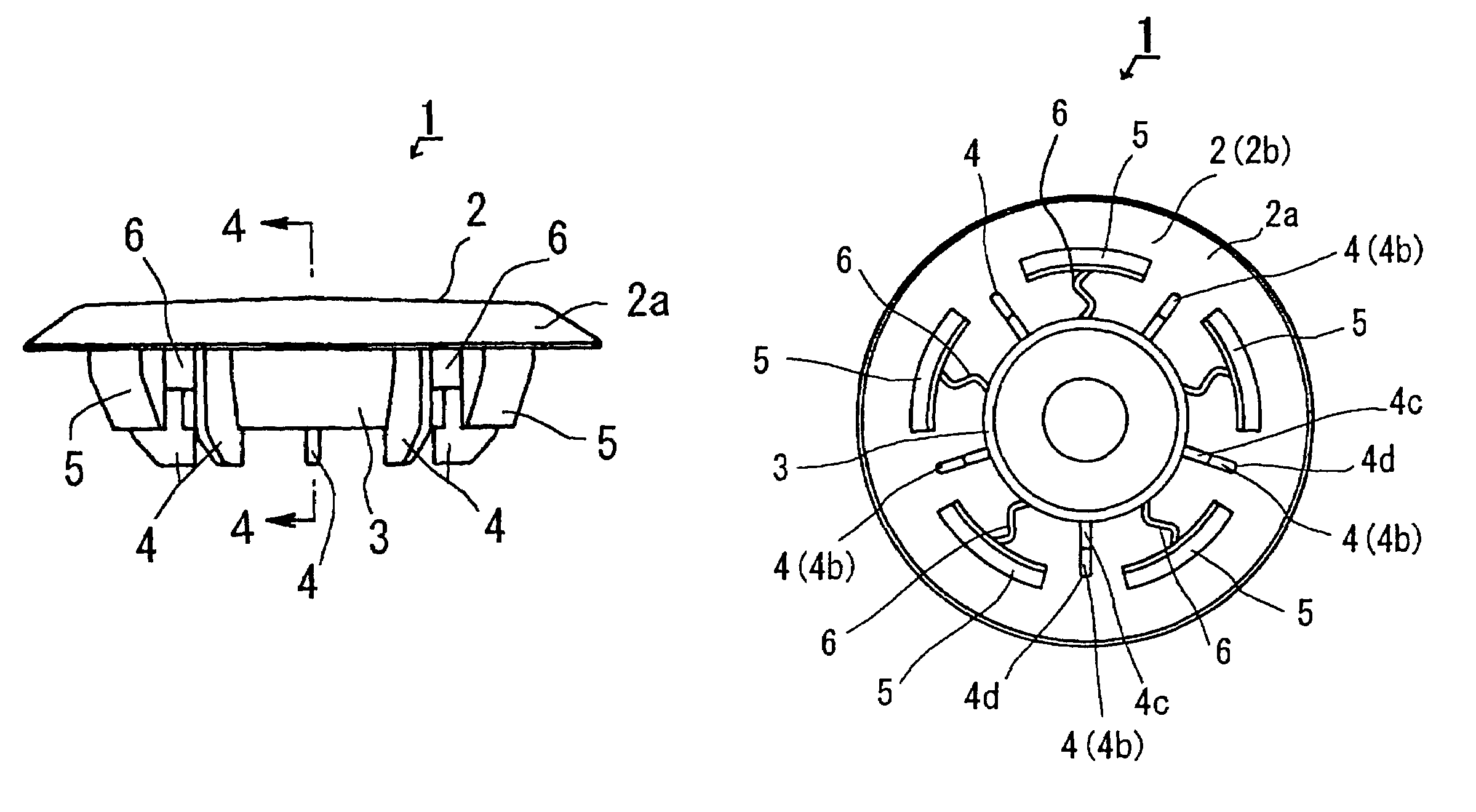
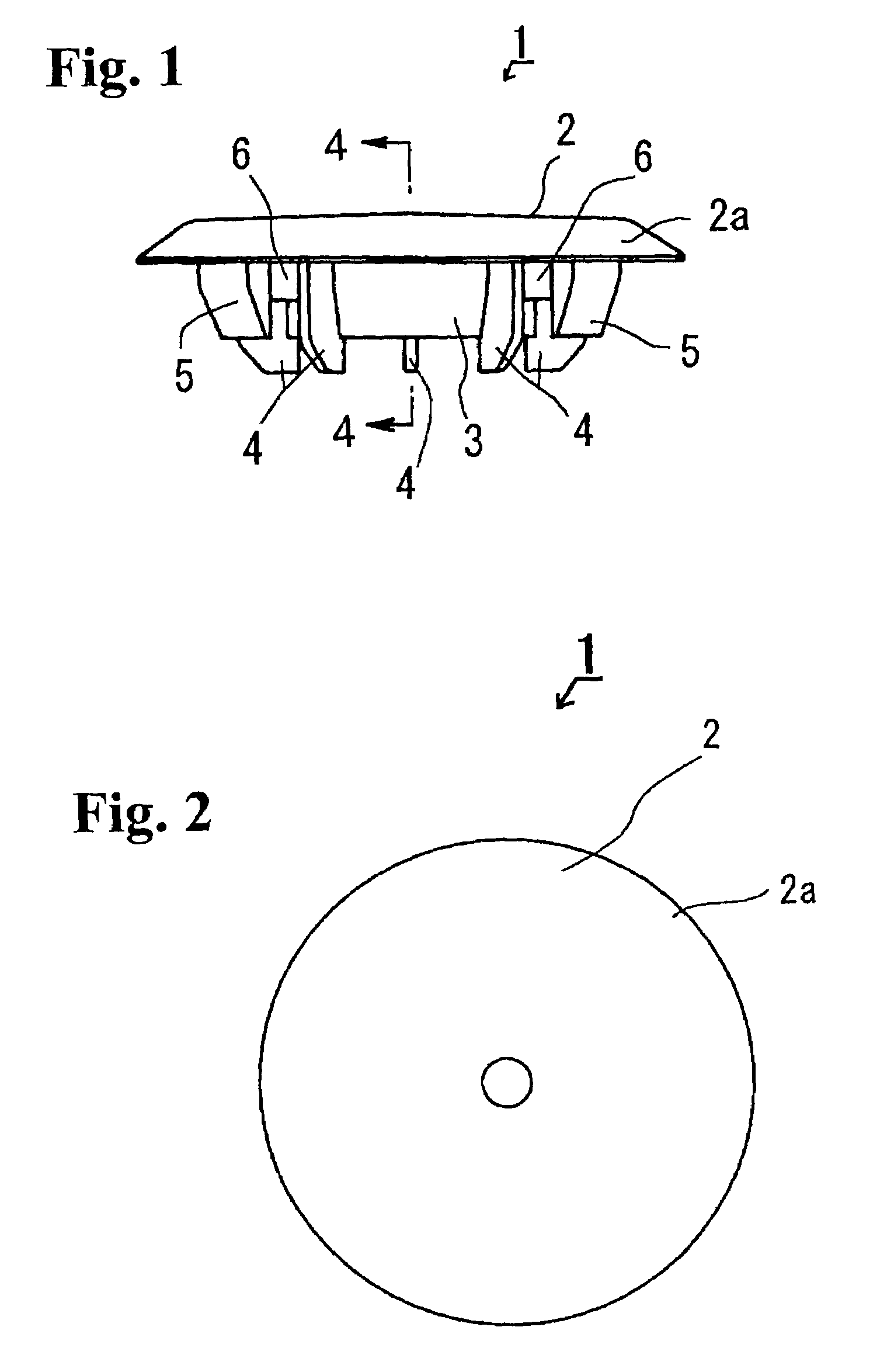
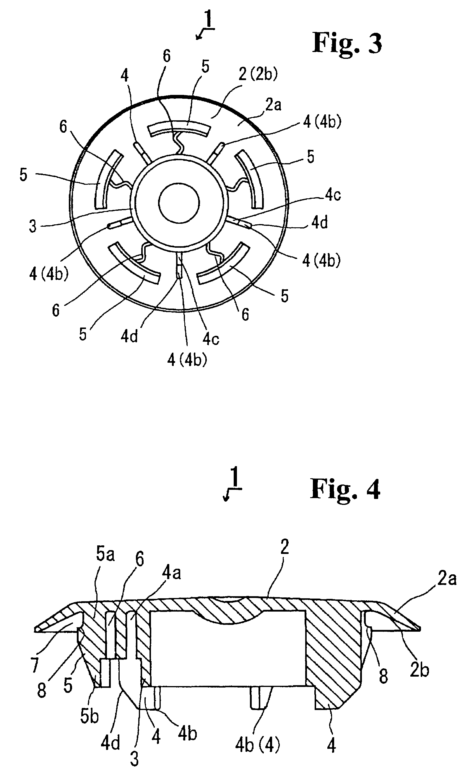
[0026]Hereinafter, preferred embodiments of the present invention will be explained with reference to the accompanying drawings. In FIGS. 1-4, reference numeral 1 designates a hole plug according to the embodiment. The hole plug 1 includes a head portion 2, a column 3, several (five in this embodiment) guide portions 4, several (five in this embodiment) uprising plates 5 constituting the foot portion, and several (five in this embodiment) supporting portions 6 as a supporting device. Each component 2-6 is integrally formed of a synthetic resin such as polyethylene and the like.

[0027]The head portion 2 is a thin plate and formed in a circular disc shape. Most of the head portion 2 is formed in a flat shape except a rim 2a. The rim 2a is formed in a slope inclined toward a back surface 2b of the head portion 2 outwardly in the radial direction of the head portion 2 for providing elasticity upon bending.

[0028]The column 3 projects from the back surface 2b of the head portion 2. The col...


PUM


Abstract

A hole plug includes a head portion and a foot portion projecting from a back surface of the head portion to be inserted into a hole to be blocked. The foot portion has a cylindrical shape formed of several uprising plates extending from the back surface of the head portion. An engaging step portion is formed at a base end of each uprising plate for holding a rim of the hole to be blocked together with the head portion. A supporting device is formed at an inside of each uprising plate for limiting bending of each uprising plate inwardly in the radial direction.

Description

BACKGROUND OF THE INVENTION AND RELATED ART STATEMENT[0001]The present invention relates to a hole plug for sealing a hole formed on a plate member such as a steel plate used for various types of products such as an automobile.[0002]A hole plug basically includes a head portion and a foot portion projecting from a back surface of the head portion to be inserted into a hole to be blocked. As disclosed in Patent Reference No. 1, recently, this type of hole plug has a head portion having a roughly flat top surface without an opening for an aesthetic reason, and a foot portion having a foot portion main member projecting from a back surface of the head portion and several engaging claws turning toward the head portion side from an end of the foot portion main member for easy insertion into the hole. Each engaging claw can deforms (swing) around an end of the foot portion main member as a pivot in a radial direction of the foot portion main member. According to such a hole plug, when the...

Claims


Application Information

Patent Timeline
IPC IPC(8): F16B19/00B62D25/24F16B37/14
CPCB62D25/24Y10T24/309
Inventor NAGASAWA, NORIMASAOBAYASHI, NOBORU
Owner NIFCO INC
Why Eureka
Try Eureka