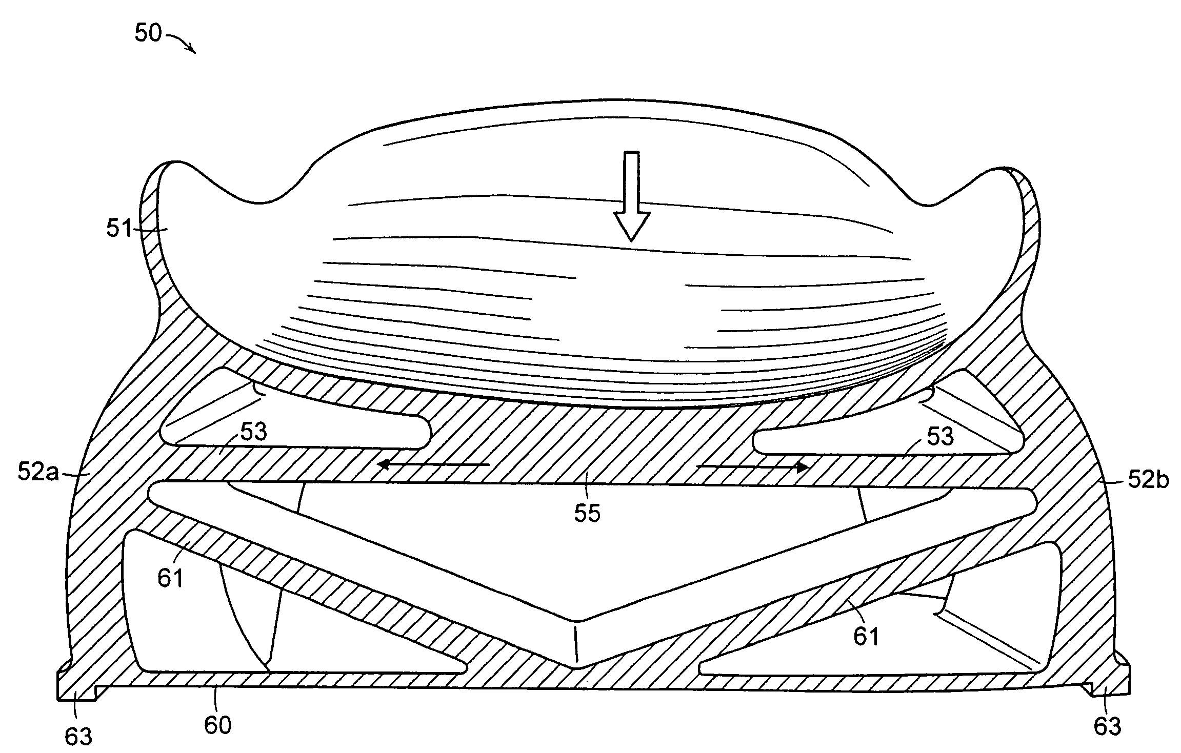
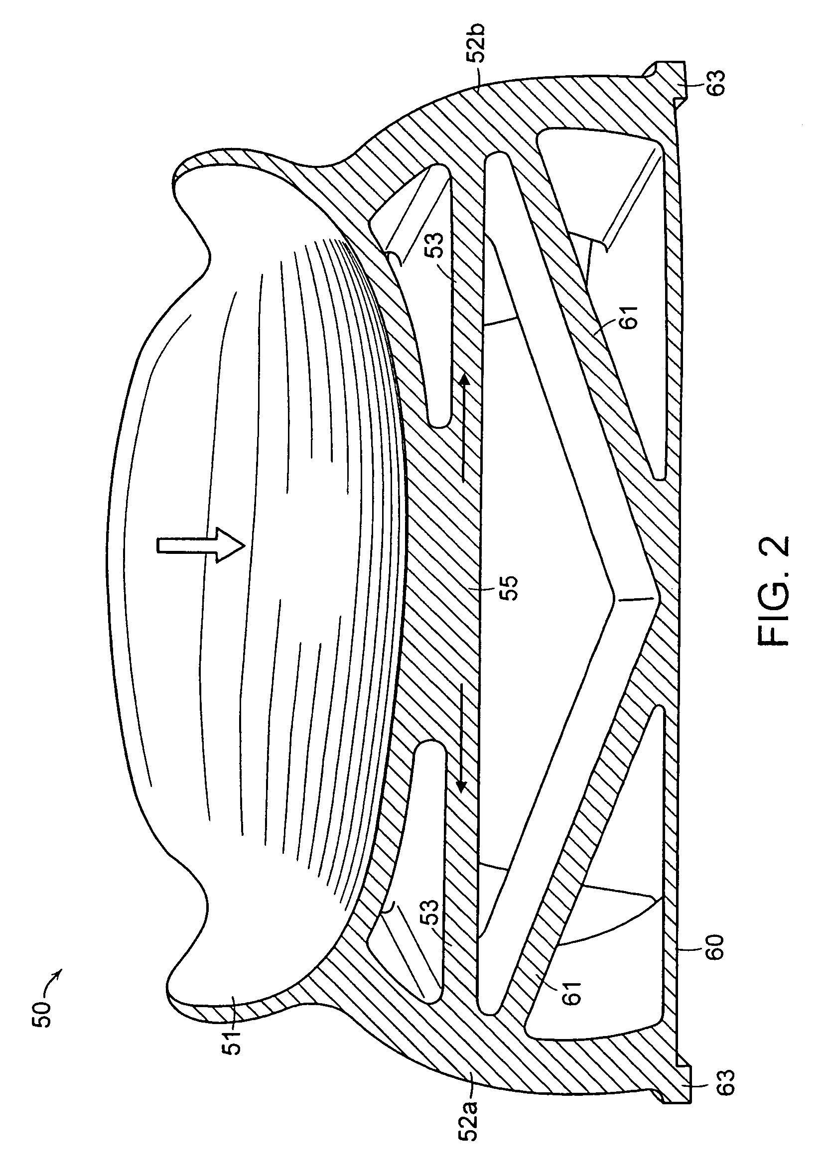
[0008]The present invention includes a shoe sole with a structural heel part. The heel part includes a heel cup or a heel rim having a shape that substantially corresponds to the shape of a heel of a foot. The heel part further includes a plurality of side walls arranged below the heel cup or the heel rim and at least one tension element interconnecting at least one of the side walls with another side wall or with the heel cup or the heel rim. The load of the first ground contact of a step cycle is effectively cushioned not only by the elastically bending stiffness of the side walls, but also by the elastic stretchability of the tension element, which acts against a bending of the side walls.
[0009]With the aforementioned components provided as a single piece of unitary construction, a high degree of structural stability is obtained and the heel is securely guided during a deformation movement of the heel part. Accordingly, there is a controlled cushioning movement so that injuries in the foot or the knee resulting from extensive pronation or supination are avoided. Furthermore, a single piece construction in accordance with one embodiment of the invention facilitates a very cost-efficient manufacture, for example by injection molding a single component using one or more suitable plastic materials. Tests have shown that a heel part in accordance with the invention has a lifetime of up to four times longer than heel constructions made from foamed cushioning elements. Furthermore, changing the material properties of the tension element facilitates an easy modification of the dynamic response properties of the heel part to ground reaction forces. The requirements of different kinds of sports or of special requirements of certain users can, therefore, be easily complied with by means of a shoe sole in accordance with the invention. This is particularly true for the production of the single piece component by injection molding, since only a single injection molding mold has to be used for shoe soles with different properties.
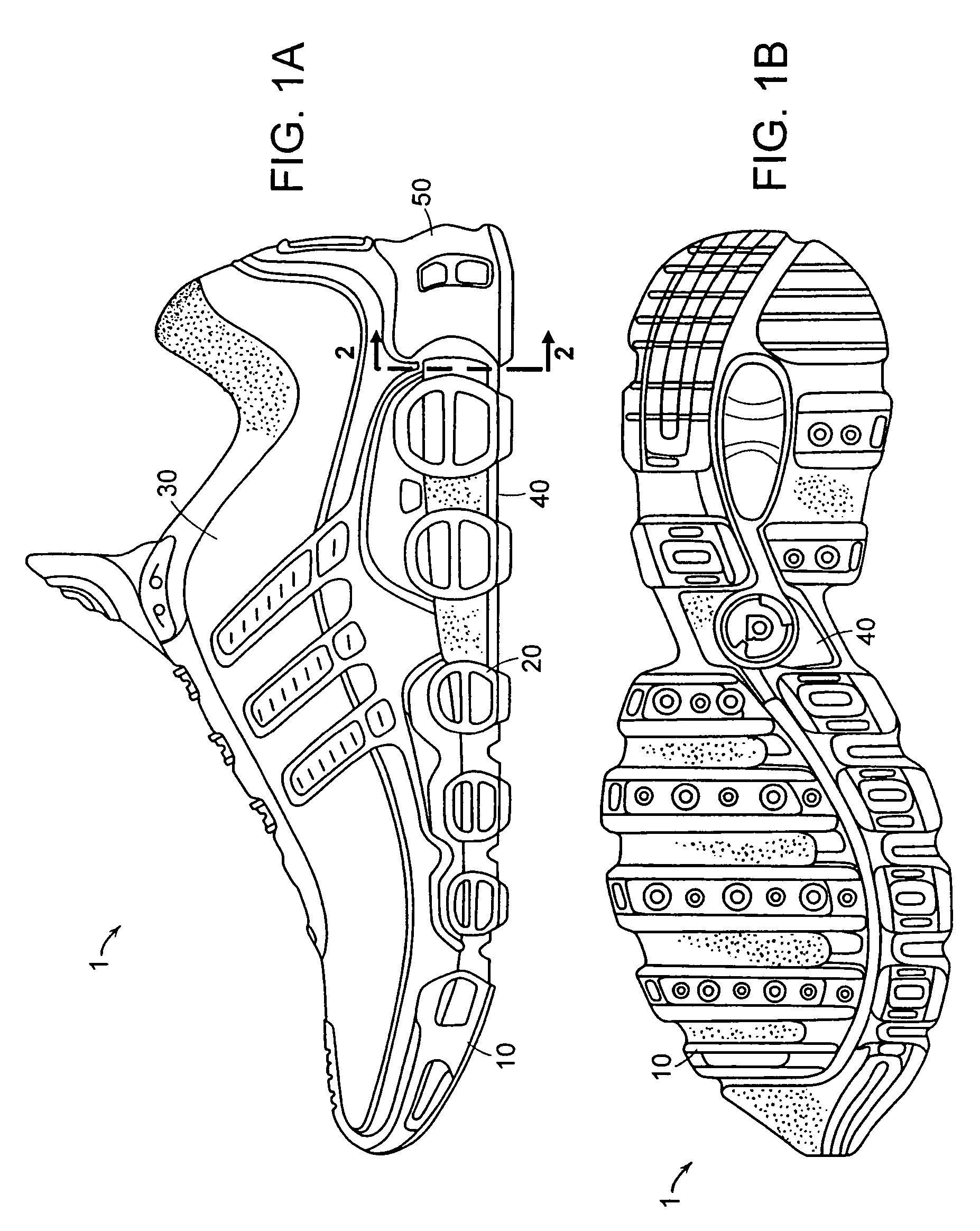
[0012]In various embodiments of the foregoing aspects of the invention, the heel part includes side walls interconnected by the tension element. At least one of the side walls defines one or more apertures therethrough. The size and the arrangement of the aperture(s) can influence the cushioning properties of the heel part during a first ground contact. Besides being an adaptation of the cushioning properties, weight can be reduced. The exact arrangement of the apertures and the design of the side walls and of the other elements of the heel part can be optimized, for example, with a finite-element model. In addition, the heel part can define one or more apertures therethrough, the size and arrangement of which can be selected to suit a particular application. In one embodiment, the heel part is a heel rim including a generally centrally located aperture. Additionally, a skin can at least partially cover or span any of the apertures. The skin can be used to keep dirt, moisture, and the like out of the cavities formed within the heel part and does not impact the structural response of the side walls. The side walls continue to function structurally as separate independent walls.
[0013]In one embodiment, the heel part includes a lateral side wall and a medial side wall that are interconnected by the tension element. As a result, a pressure load on the two side walls from above is transformed into a tension load on the tension element. Alternatively or additionally, the tension element can interconnect all of the side walls, including the rear wall. The at least one side wall can include an outwardly directed curvature. The tension element can engage at least two of the plurality of side walls substantially at a central region of the respective side walls. The tension element can extend below the heel cup and be connected to a lower surface of the heel cup at a central region thereof. This additional connection further increases the stability of the single piece heel part.
[0014]Further, the heel part can include a substantially horizontal ground surface that interconnects the lower edges of at least two of the plurality of side walls. In one embodiment, an outer perimeter of the horizontal ground surface extends beyond lower edges of the side walls. The horizontal ground surface is generally planar; however, the ground surface can be curved or angled to suit a particular application. For example, the horizontal ground surface can be angled about its outside perimeter or can be grooved along its central region to interact with other components. Additionally, the heel part can include at least one reinforcing element. In one embodiment, the at least one reinforcing element extends in an inclined direction from the horizontal ground surface to at least one of the plurality of the side walls. The at least one reinforcing element can extend from a central region of the horizontal ground surface to at least one of the plurality of side walls. In various embodiments, the at least one reinforcing element and the tension element substantially coterminate at the side wall at, for example, a central region thereof. In one embodiment, the heel part has a symmetrical arrangement of two reinforcing elements extending from a central region of the ground surface to the side walls, wherein the two reinforcing elements each terminate in the same, or substantially the same, area as the tension element. As a result, the single piece heel part has an overall framework-like structure leading to a high stability under compression and shearing movements of the sole.
[0015]Furthermore, at least one of the heel cup, the side walls, the tension element, and the reinforcing elements has a different thickness than at least one of the heel cup, the side walls, the tension element, and the reinforcing elements. In one embodiment, a thickness of at least one of the heel cup, the side walls, the tension element, and the reinforcing elements varies within at least one of the heel cup, the side walls, the tension element, and the reinforcing elements. For example, the cushioning behavior of the heel part may be further adapted by side walls of different thicknesses and by changing the curvature of the side walls. Additionally or alternatively, the use of different materials, for example materials of different hardnesses, can be used to further adapt the cushioning properties of the heel part. The heel part can be manufactured by injection molding a thermoplastic urethane or similar material. In one embodiment, the heel part can be manufactured by multi-component injection molding at least two different materials. The heel part can be substantially or completely free from foamed materials, insofar as no purposeful foaming of the material(s) used in forming the heel part is carried out by, for example, the introduction of a chemical or physical process to cause the material to foam. Alternatively, foamed materials can be disposed within the various cavities defined within the heel part by the side walls, tension elements, and reinforcing elements, to improve the cushioning properties of the heel part.

