High intensity radial field magnetic actuator

a magnetic actuator, high intensity technology, applied in the field of magnetism, can solve the problems of mechanical actuators at such a small size, unreliability, and parts of wear and tear, and achieve the effect of reducing the number of mechanical actuators

Inactive Publication Date: 2008-04-01
ENG MATTERS
View PDF14 Cites 18 Cited by
  • Summary
  • Abstract
  • Description
  • Claims
  • Application Information

AI Technical Summary

Problems solved by technology

One of the problems with mechanical actuators is that parts of the mechanical actuators have a tendency to wear down.
When the springs become less elastic and the pivoting joints become worn, the valves cease to operate in an efficient manner.
Mechanical actuators at such a small size are extremely unwieldy and unreliable.
Thus, a heretofore unaddressed need exists in the industry to address the aforementioned deficiencies and inadequacies.

Method used


Image

  • High intensity radial field magnetic actuator
  • High intensity radial field magnetic actuator
  • High intensity radial field magnetic actuator

Examples


Embodiment Construction

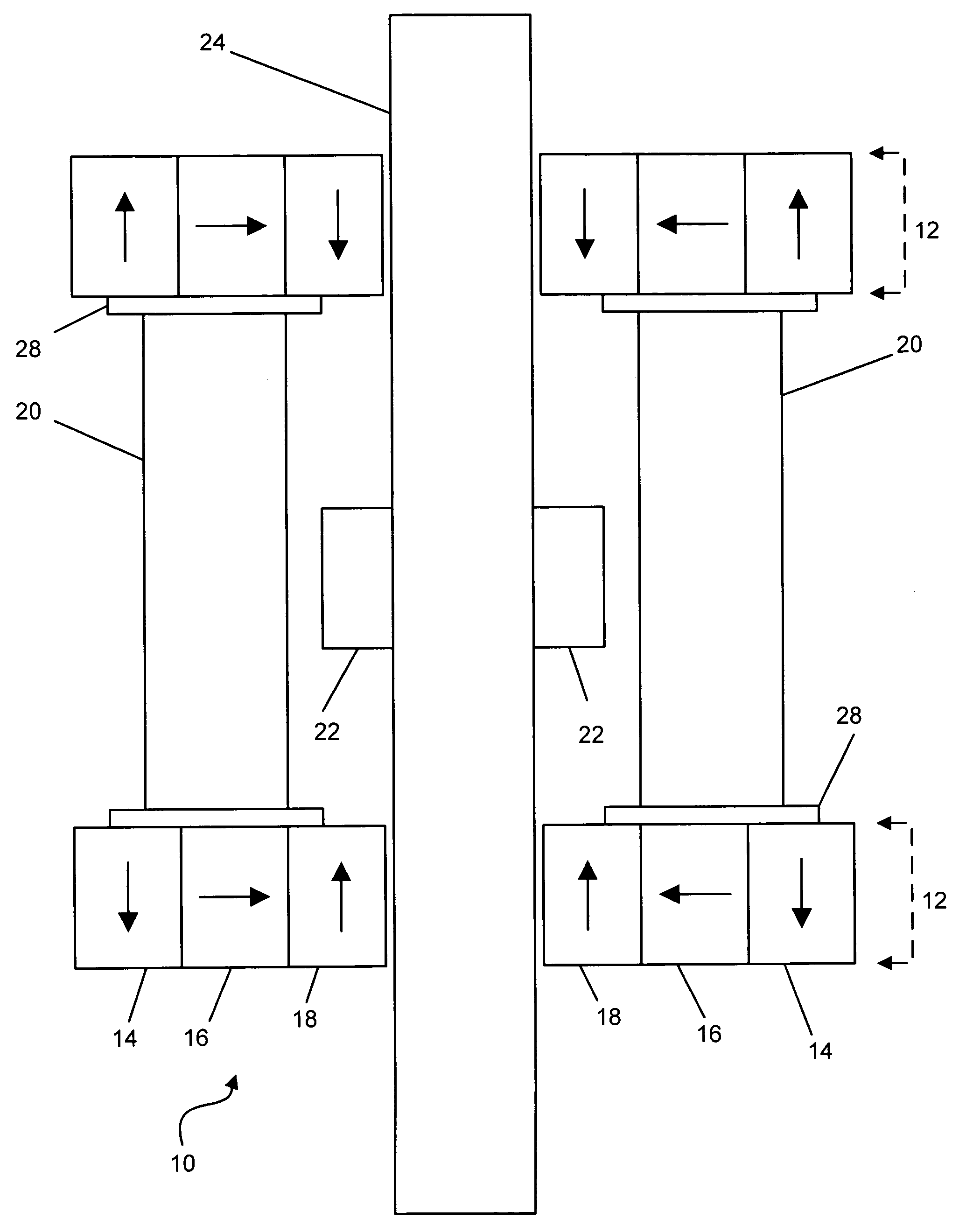
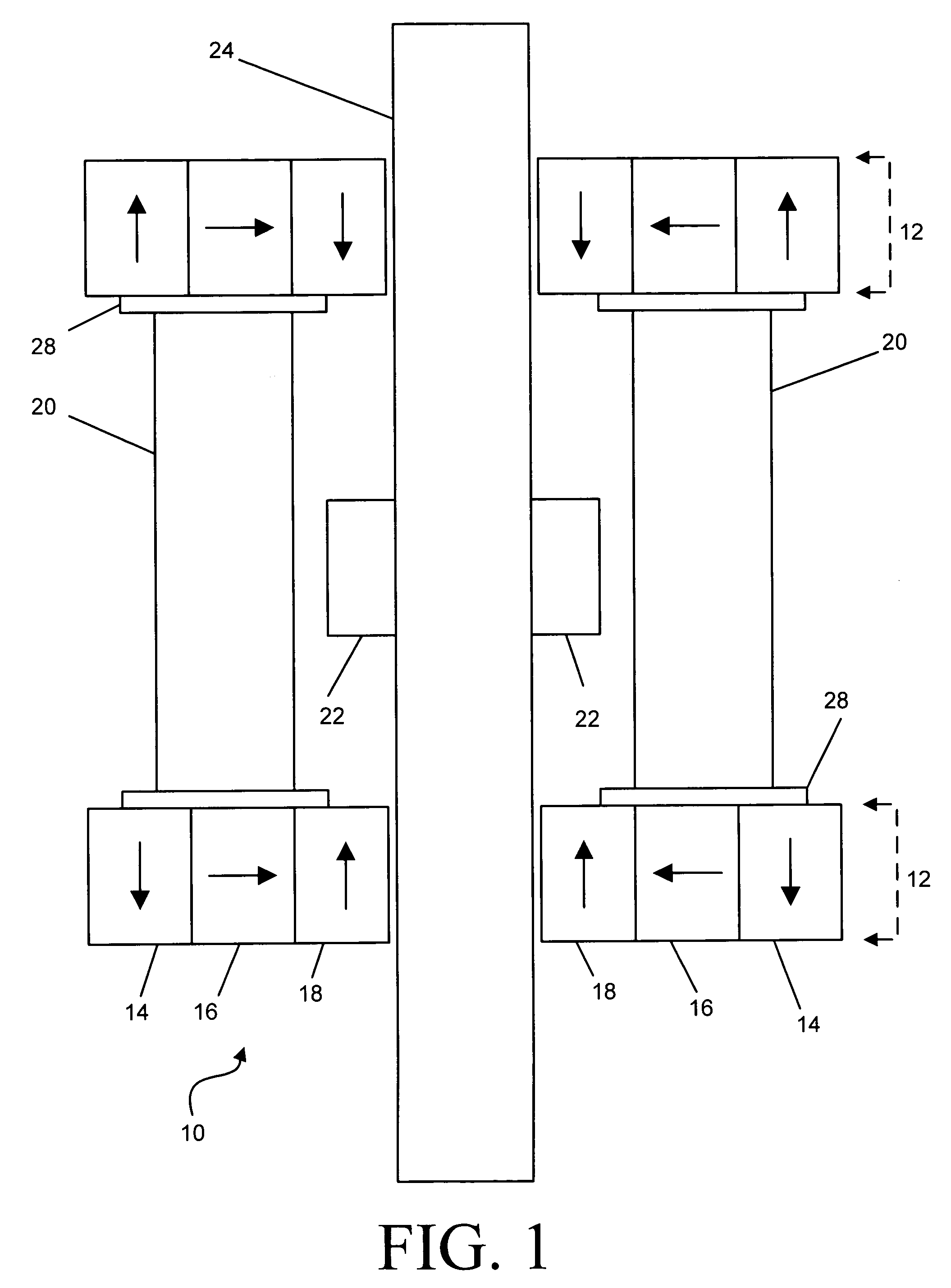
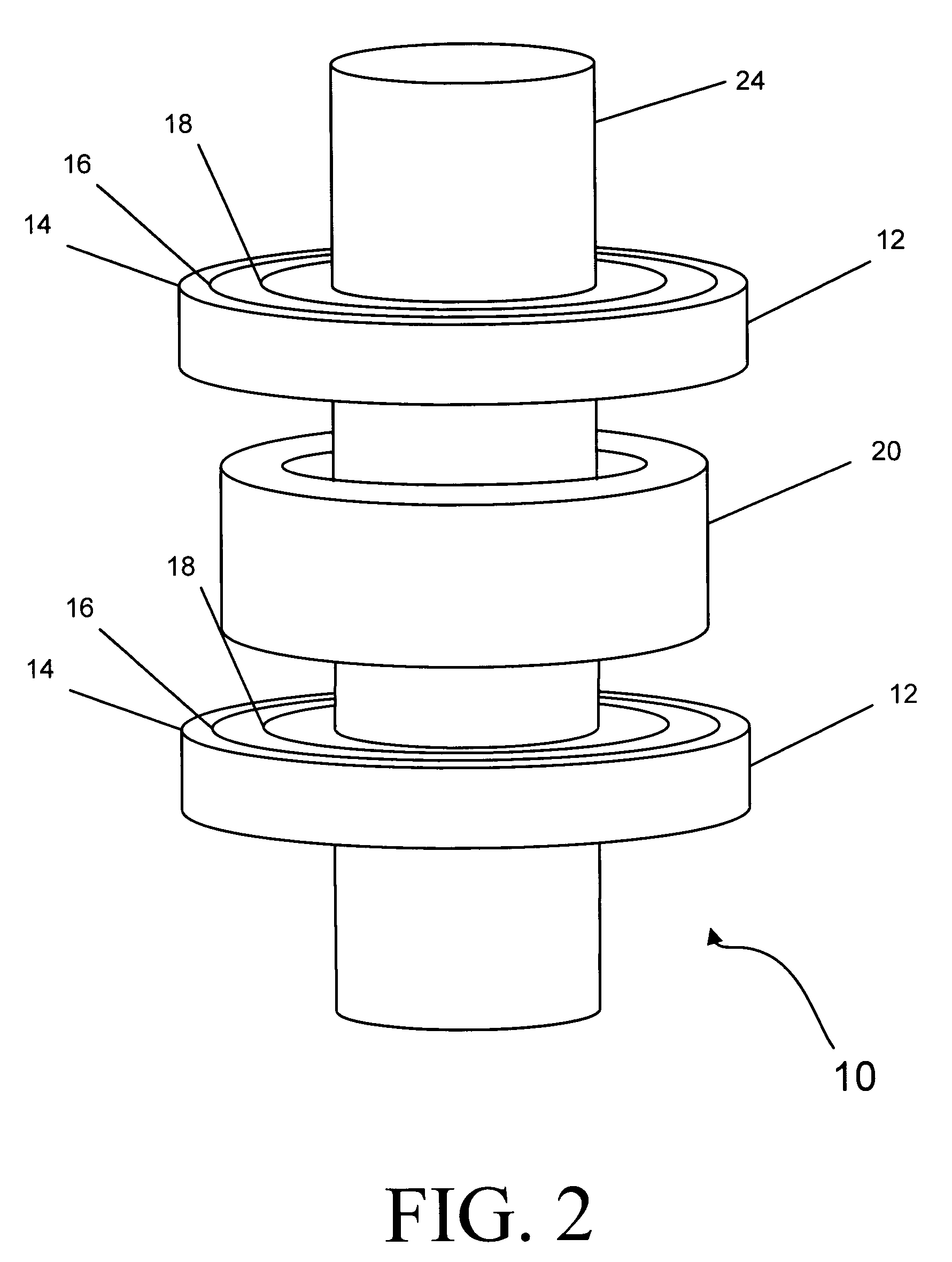
[0033]FIG. 1 is a cross-sectional view and FIG. 2 is a perspective view of a first exemplary embodiment of the magnetic actuator 10. At least one set of two nested magnet arrays 12 is provided, each nested magnetic array 12 having an outer magnet 14, a middle magnet 16, and an inner magnet 18. The magnetization of the three magnets 14, 16, 18 is illustrated by arrows shown within the magnets 14, 16, 18. The outer magnet 14 has a magnetization pointing in an at least partially axial direction. The middle magnet 16 has a magnetization substantially perpendicular to the magnetization of the outer magnet 14. The inner magnet 18 has a magnetization directed substantially anti-parallel to the magnetization of the outer magnet 14. Comparing the magnetization of the magnets 14, 16, 18 in the two nested magnet arrays 12, the magnetizations of the two outer magnets 14 are anti-parallel, the magnetizations of the two middle magnets 16 are parallel, and the magnetizations of the two inner magne...


PUM

PropertyMeasurementUnit
heightaaaaaaaaaa
magnetic fieldaaaaaaaaaa

Abstract

At least one set of two magnets is provided, at least one of the magnets having an outer magnet portion, a middle magnet portion, and an inner magnet portion. The outer magnet portion has a magnetization pointing in an at least partially axial direction. The middle magnet portion has a magnetization substantially perpendicular to the magnetization of the outer magnet portion. The inner magnet portion has a magnetization directed substantially anti-parallel to the magnetization of the outer magnet portion. The apparatus also includes at least one electrically conductive coil positioned at least partially between the set of two magnets. At least one substantially magnetically permeable object is positioned at least partially between the set of two magnets. A rod is integral with the substantially magnetically permeable object.

Description

CROSS-REFERENCES[0001]The present application claims benefit of pending U.S. patent application Ser. No. 10 / 899,794, filed on Jul. 27, 2004, titled, “High Intensity Radial Field Magnetic Array and Actuator”, the disclosure of which is incorporated herein by reference.FIELD OF THE INVENTION[0002]The present invention is related to the field of magnetism, and in particular, is related to direct drive actuators employing a radial magnetic field and conducting coil acting on an element of a valve.BACKGROUND OF THE INVENTION[0003]Actuators are traditionally a mechanical art. Most actuators contain valves, springs, and pivoting elements that move the valves. One of the problems with mechanical actuators is that parts of the mechanical actuators have a tendency to wear down. When the springs become less elastic and the pivoting joints become worn, the valves cease to operate in an efficient manner. An actuator with fewer moving parts would tend to outlast the traditional mechanical actuato...

Claims


Application Information

Patent Timeline
Patent Type & Authority Patents(United States)
IPC IPC(8): H01F7/00H01F7/08H01F7/06H01F7/20
CPCH01F7/0242H01F7/066H01F7/1615H01F7/20H02K41/0352
Inventor WRIGHT, ANDREW M.COPE, DAVID
Owner ENG MATTERS
Why Eureka
Try Eureka