Double-release bar for a cow stanchion apparatus

a technology of stanchion and double-release bar, which is applied in the field of double-release bar for cow stanchion apparatus, can solve the problems of higher milk production, chafing of the cow's skin, and discomfort of the cow, and achieves the effect of wide opening for the cattle and positive and quick locking up

Inactive Publication Date: 2008-04-08
ALBERS JR TEO
View PDF10 Cites 4 Cited by
  • Summary
  • Abstract
  • Description
  • Claims
  • Application Information

AI Technical Summary

Benefits of technology

[0003]The improved cattle stanchion apparatus of the present invention utilizes a plurality of pairs of like pivoted release stanchion bars in place of the pivoted single release stanchion bars employed in prior art cattle stanchion apparatus. The double-release stanchion bar arrangement of the present invention permits a shorter travel of the release stanchion bars for locking up the cattle, provides a more positive and quicker locking up of the cattle, requires half the effort to lock up the cattle, provides a wider opening for the cattle, and allows bulls to enter the stanchion apparatus, rather than solely cows. The wider opening also allows for a more inviting entry for timid or short cows.
[0004]The most important advantage of the cattle stanchion apparatus of the present invention is that it allows for greater cow comfort, and applies less stress to the cows, resulting in increased milk production as compared to prior art cattle stanchion apparatus. In this regard, conventional prior art cow stanchion apparatus generally include a plurality of like fixed stanchion and release structures, each release stanchion being pivotally secured to a fixed stanchion. A cow enters the head opening defined between a release stanchion and its fixed stanchion when the cow's head engages the release stanchion. During feeding, a cow swings its head as she reaches for feed. During such swinging movement, the cow's neck contacts the hard unyielding surface of the fixed stanchion as she reaches for food causing discomfort to the cow. Contact of the cow's neck with the hard surface of the fixed stanchion can result in chafing of a cow's skin when she fights to reach for feed located at the sides of her feeding stall.
[0005]The cattle stanchion apparatus of the present invention solves the above-described problem by providing a plurality of like cow feeding stations each having a release stanchion assembly which includes a pair of release stanchion bars pivotally supported for free swinging movement towards and away from one another when engaged by the neck of a feeding cow as such cow swings her head to reach her feed. Accordingly, the cow does not have to rub her neck on a hard fixed stanchion bar when she reaches for feed located at the sides of her feeding stall. The cow will therefore feel comfortable during feeding, stay in the cattle stanchion longer, and accordingly consume more feed than she would if confined in a prior art stanchion apparatus. Higher food consumption results in higher milk production. Moreover, since the release stanchion release bars swing with the cow's neck as she reaches for food, chafing of the cow's neck can be eliminated.
[0006]Another advantage of the cattle stanchion apparatus of the present invention is that its operation is not affected by extreme temperature conditions.

Problems solved by technology

During such swinging movement, the cow's neck contacts the hard unyielding surface of the fixed stanchion as she reaches for food causing discomfort to the cow.
Contact of the cow's neck with the hard surface of the fixed stanchion can result in chafing of a cow's skin when she fights to reach for feed located at the sides of her feeding stall.
Higher food consumption results in higher milk production.

Method used


Image

  • Double-release bar for a cow stanchion apparatus
  • Double-release bar for a cow stanchion apparatus
  • Double-release bar for a cow stanchion apparatus

Examples


first embodiment

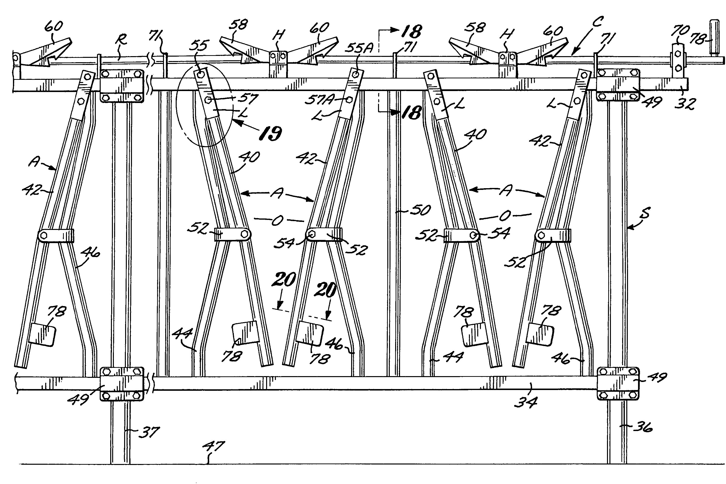
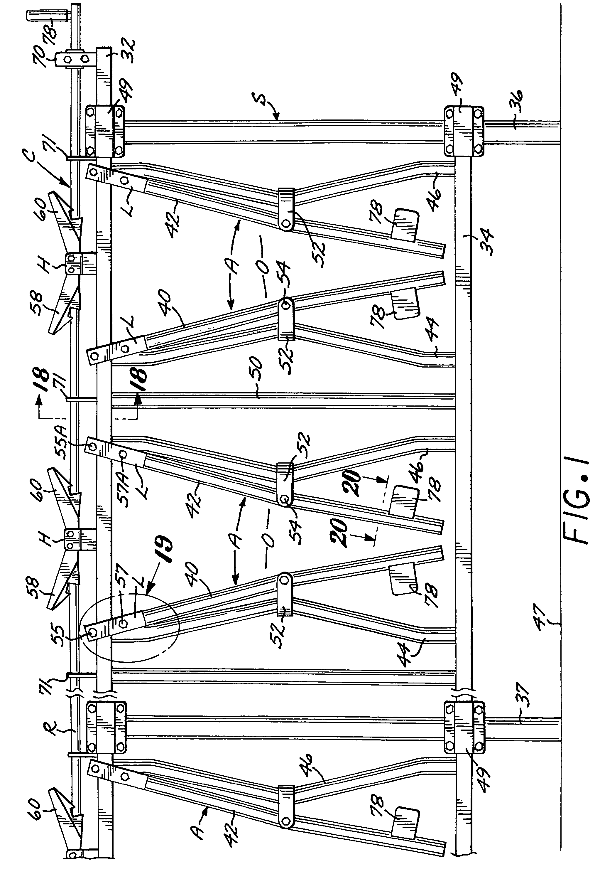
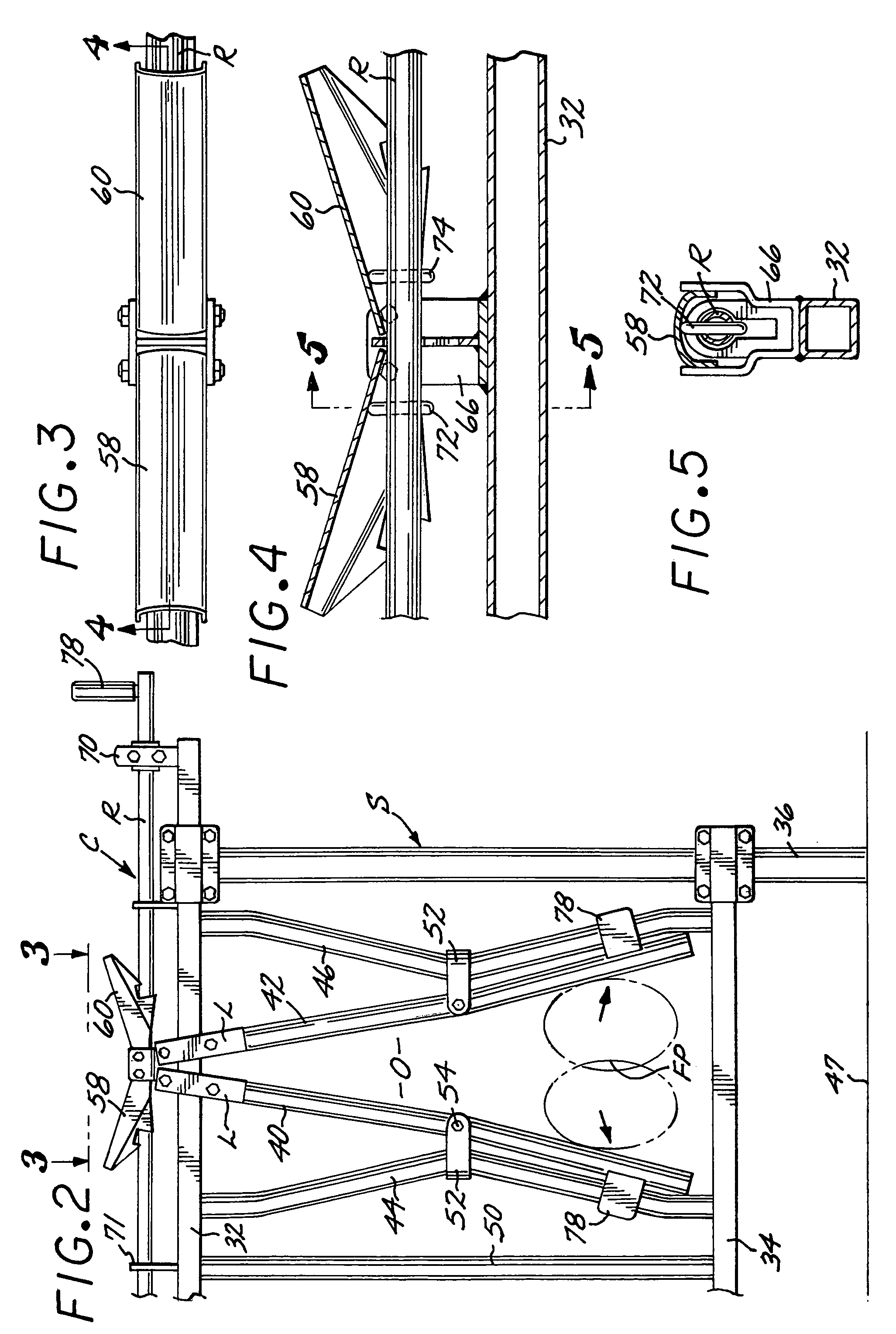
[0037]Referring to FIGS. 1-20 of the drawings, there is shown the double-release cattle stanchion bar apparatus embodying the present invention. Such apparatus includes a fixed support structure S, which includes top and bottom rails 32 and 34 respectively, shown fixed to an end post 36 and a plurality of intermediate posts 37. A plurality of double release stanchion bar assemblies A are spaced along the length of the top and bottom rails. Each assembly includes a pair of facing release stanchion bars 40, 42 of like construction and mirror images of one another. The intermediate portions of each release stanchion bar is pivotally connected to the intermediate portion of a fixed stanchion 44, 46. The intermediate portions of the fixed stanchions extend out of the vertical position towards one another. With this arrangement, the release stanchion bars 40, 42 can swing simultaneously towards and away from one another in accordance with the operation of a release stanchion bar control a...

second embodiment

[0045]Referring now to FIGS. 21-44, there is shown another preferred form of cattle stanchion apparatus embodying the present invention utilizing latching system for controlling operation of the stanchion release bars. Like components of the stanchion bar assemblies in FIGS. 21-44 bear primed reference numbers with respect to FIGS. 1-20.

[0046]The second form of cattle stanchion apparatus shown in FIGS. 21-44 includes a fixed support structure S′ which includes top and bottom rails 32′ and 34′, respectively, shown fixed to an end post 36′ and a plurality of intermediate posts (not shown). A plurality of double-release stanchion bar assemblies A′ are spaced along the length of the top and bottom rails. Each stanchion bar assembly A′ includes a pair of stanchion release bars 40′, 42′ of like construction and mirror images of one-another. The intermediate portions of each stanchion release bar is pivotally connected to the intermediate portion of a fixed release stanchion carrier bar 44...


PUM


Abstract

Cow stanchion apparatus having a fixed support structure that carries a plurality of pairs of like double release stanchion bars which simultaneously swing towards and away from one another to control movement of cattle relative to such apparatus. The stanchion release bars are disposed in the path of vertically movable flaps which lock and unlock the stanchion release bars for relative swinging movement. The flaps are operatively connected to a positioner rod that is manipulated by a dairyman.

Description

CROSS-REFERENCE TO RELATED APPLICATION[0001]The application is a continuation of my patent application Ser. No. 10 / 669,486 filed Sep. 24, 2003 now U.S. Pat. No. 6,834,620, which was in turn a continuation-in-part of my patent application Ser. No. 10 / 361,134 filed Feb. 6, 2003 and now U.S. Pat. No. 6,776,124, which is incorporated herein by reference in its entirety.BACKGROUND OF THE INVENTION[0002]The present invention relates to cattle stanchion apparatus and more particularly to an improved cattle stanchion apparatus utilizing double release stanchion bars. Prior cattle stanchion apparatus have utilized single release stanchion bars for controlling movement of cattle into and out of such stanchion apparatus. Examples of such prior cattle stanchion apparatus are shown in Albers U.S. Pat. Nos. 4,037,566; 4,051,813; 4,185,592; 4,476,815; and 4,495,897. See also Hatfield U.S. Pat. No. 4,867,105 and DaSilveira U.S. Pat. No. 4,930,452.SUMMARY OF THE INVENTION[0003]The improved cattle st...

Claims


Application Information

Patent Timeline
Patent Type & Authority Patents(United States)
IPC IPC(8): A01K15/04A01K1/06
CPCA01K1/0606
Inventor ALBERS, JR., TEO
Owner ALBERS JR TEO
Why Eureka
Try Eureka