Low profile latching connector and pull tab for unlatching same

a low-profile, latching technology, applied in the direction of substation/switching arrangement details, coupling device connections, electrical devices, etc., can solve the problems of increasing the difficulty of disengaging the latch mechanism of the plug connector, the inability to use low-profile, high-density receptacle connectors, etc., to facilitate the operation of the latch mechanism, easy grasping, and soft area

Active Publication Date: 2008-04-08
MOLEX INC
View PDF25 Cites 121 Cited by
  • Summary
  • Abstract
  • Description
  • Claims
  • Application Information

AI Technical Summary

Benefits of technology

[0008]Accordingly, it is a general object of the present invention is to provide a low profile connector with a latching mechanism that secures it to an opposing receptacle.
[0009]Another object of the present invention is to provide a low profile plug connector that is usable in high-density electronic devices, but which has a latching mechanism that is not positioned alongside of the plug connector housing, and in which the latching mechanism is simple to assemble and simple to operate, using a minimum number of components.
[0017]In one embodiment of the invention, the actuator includes a flat grasping end with an opening that may be either grasped by a user or pulled by insertion of a finger into an opening formed in the tail end of the actuator. In another embodiment of the invention, the actuator has its tail configured into a loop, that encircles the cables entering the plug connector. The loop may be easily grasped to unlatch the plug connector from an opposing guide frame or housing. The loop and actuator are preferably formed from a plastic or other resilient material and a metal sleeve may be inserted into the loop to provide stiffness in the area encircling the cable leading to the plug connector.
[0018]In another embodiment of the invention the pull tab has a tail in the form of a loop and the loop has a non-planar configuration to it. The loop is defined by a thin rod-like member formed into a circle at the tail end of the actuator and the rod-like member has an ergonomic design in which it is deformed or contoured to fit within the widthwise dimension of the connector body. The rod-like member is further configured to bend over the cable exiting from the connector. In this manner, the rear end of the tail loop presents a more easily grasped profile than a flat tail loop, thereby facilitating the operation thereof. The tail loop takes up less space than if it were planar so as to facilitate insertion and removal of the plug connectors in tight spaces.

Problems solved by technology

A problem with many electronic connectors of this type, however, is the tendency for them to separate or be disconnected from the component to which they are connected.
One problem with the locking plug connectors such as those disclosed in the '987 patent is that they are not usable with low-profile, high-density receptacle connectors.
As connectors become smaller and as the density of receptacle connectors in electronic devices increases, the simple act of disengaging a plug connector latch mechanism becomes increasingly more difficult.
This connector has a complex mechanical structure with a plurality of parts, such that manufacturing and assembly costs will be increased.
It is constructed of many separate pieces and is relatively difficult to manufacture, and it requires excessive space at its rear end for an actuator to project.
However, the planar extent and size of the hole in this pull tab is relatively small and may prove difficult to readily grasp in tight quarters.
The pull tab is flat and lies in substantially a single plane which further increases the difficulty in reliably grasping it.

Method used


Image

  • Low profile latching connector and pull tab for unlatching same
  • Low profile latching connector and pull tab for unlatching same
  • Low profile latching connector and pull tab for unlatching same

Examples


Embodiment Construction

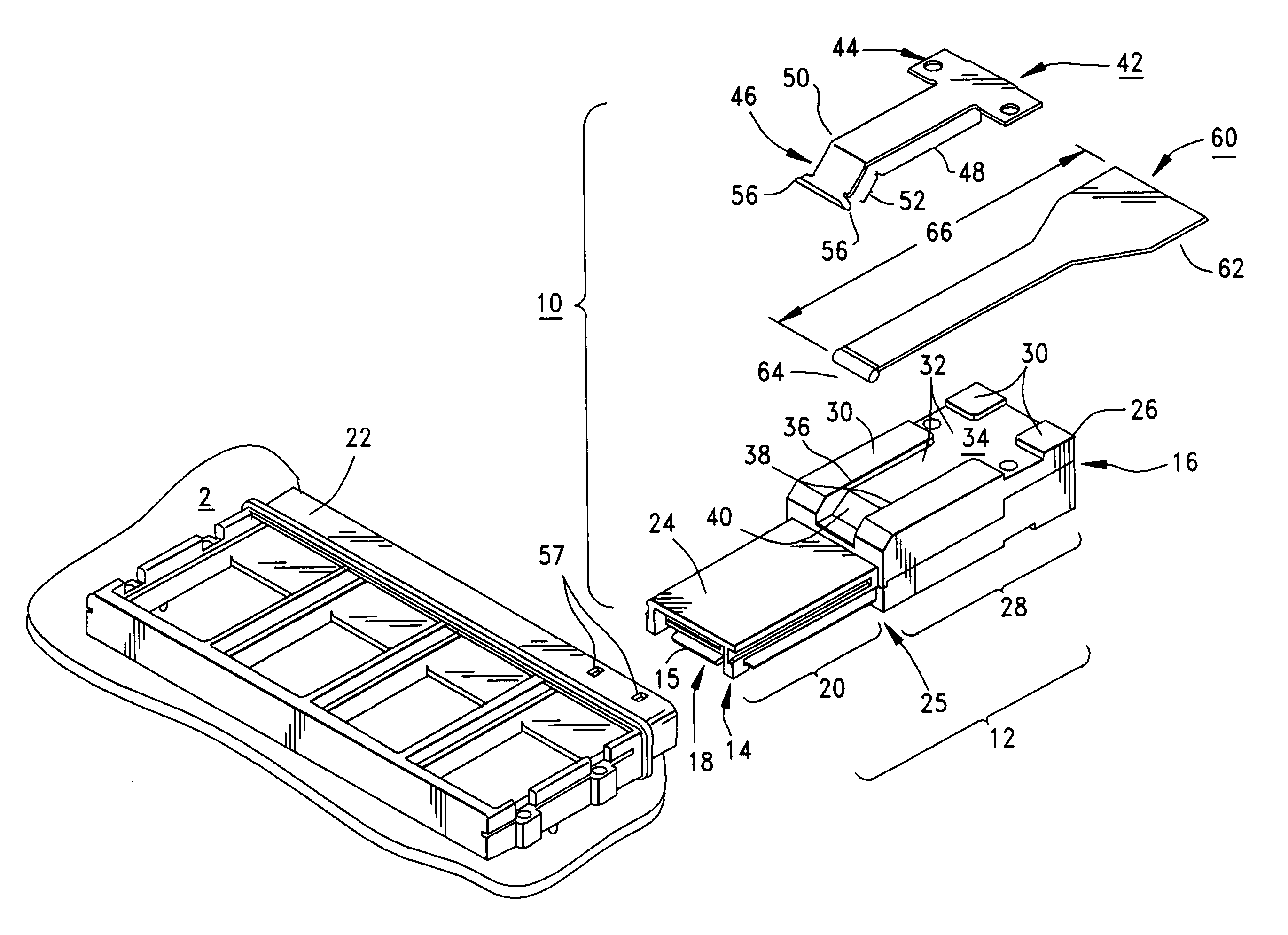
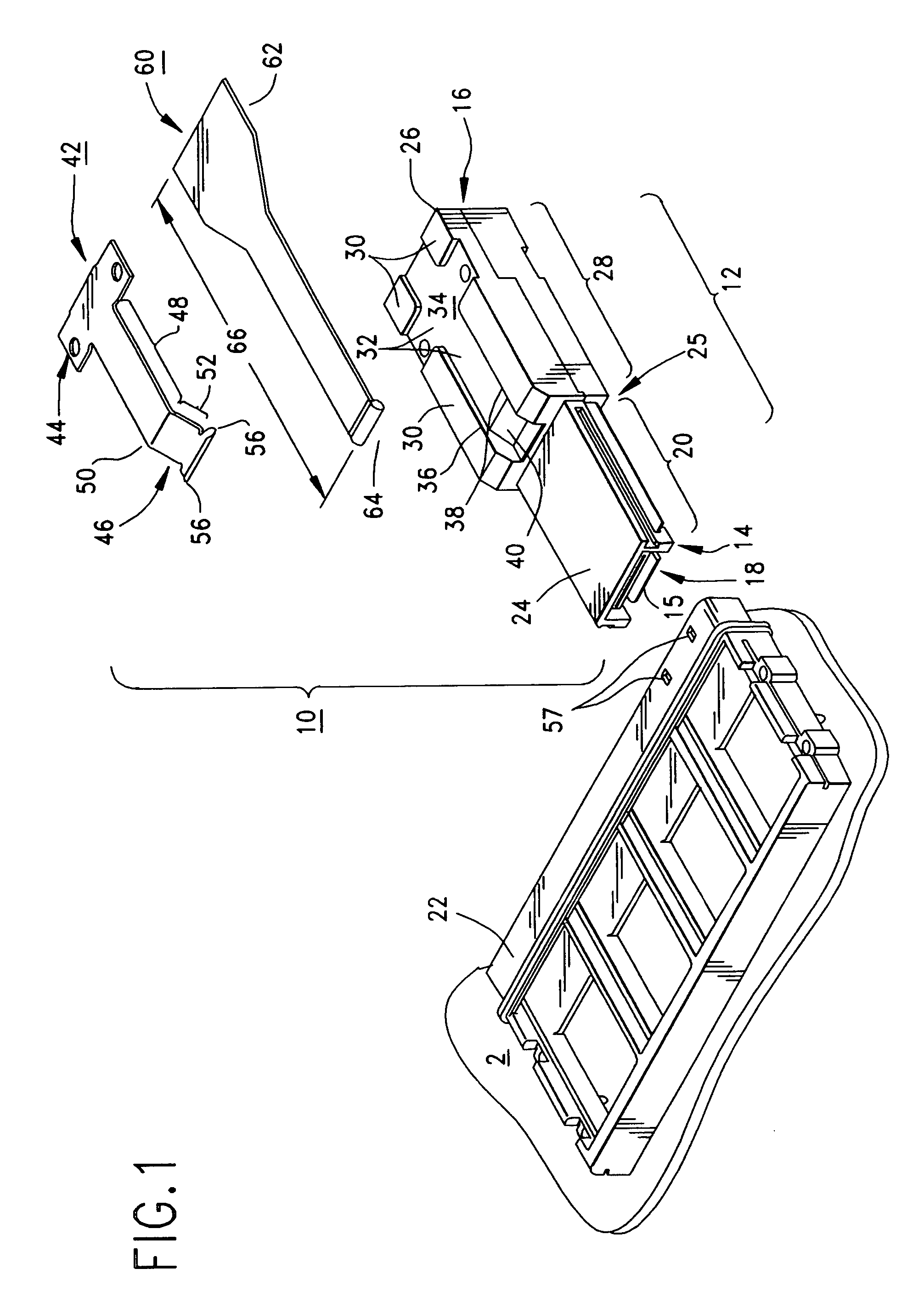
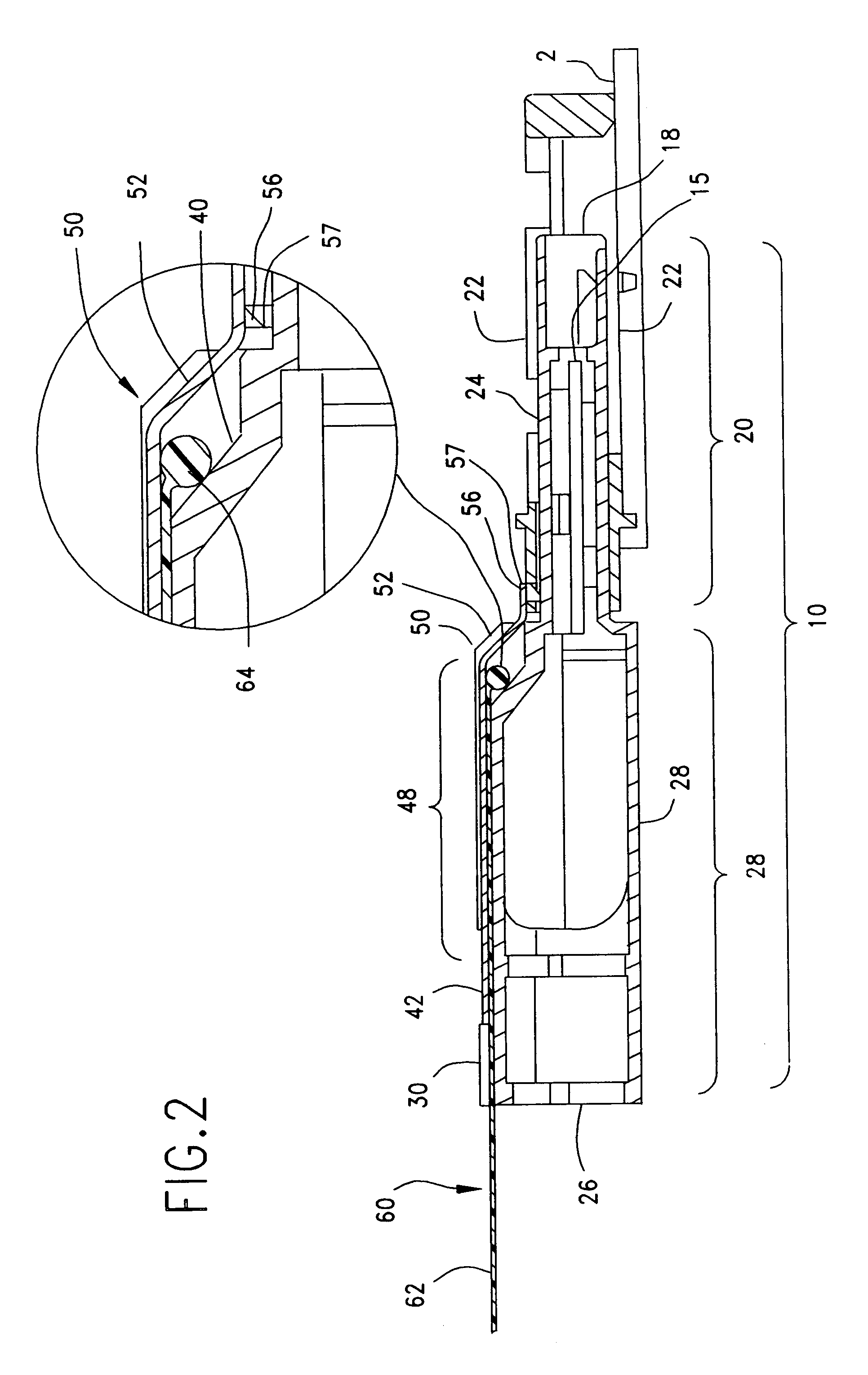
[0047]FIG. 1 is an exploded perspective view of a low-profile plug connector 10 constructed in accordance with the principles of the present invention. The plug connector 10 is seen to include an elongated connector housing 12 having two opposing ends identified in the Figures by reference numerals 14 and 16. The first, or front end, 14 of the plug connector body 12 defines a mating end 18 of the front portion 20 of the plug connector housing 12. This front portion 20 of the connector housing 12 is shown as having has the shape of a rectangular parallelpiped or cuboid, the cross section of which is rectangular. One or more electrical terminals are contained within the front shell 20 in order to make electrical contact with mating terminals in a mating receptacle connector (not shown) which is enclosed within an outer protective guide frame 22, both the receptacle connector and guide frame being mounted to a printed circuit board 2.

[0048]The dimensions of the connector housing front ...


PUM


Abstract

A small, low-profile plug connector for use with electronic devices provides a latching member with a pair of hooks that engage mating holes in a guide frame, and which can be easily delatched from the guide frame or opposing connector or housing. The hooks lock the plug connector into engagement with the frame or housing, but are readily released by way of a simple ramp and lobe mechanism in the plug connector. The ramp and lobe mechanism converts horizontal movement of a pull tab actuator into vertical movement of a latching member such that the hooks are lifted upward and disengaged from the guide frame or housing. The pull tab has a configured shape that fits within the width profile of the connector and which partially envelops the cable.

Description

REFERENCE TO RELATED APPLICATIONS[0001]This application claims priority for prior U.S. provisional Patent Application No. 60 / 817,986, filed Jun. 30, 2006.BACKGROUND OF THE INVENTION[0002]The present invention is directed to small and low-profile connectors. More particularly, the present invention is directed to pluggable-style connectors that are received within a housing, or guide frame, and which require some sort of exterior latch to retain the connector in its mated engagement with the housing or guide frame.[0003]Small and low-profile connectors, such as those used in SFP (Small Form Factor Pluggable) applications are desired in electronic devices in which space is a premium. Such connectors are widely used to make connections with routers and servers. They are small in size. A problem with many electronic connectors of this type, however, is the tendency for them to separate or be disconnected from the component to which they are connected.[0004]Connectors, and particularly p...

Claims


Application Information

Patent Timeline
Patent Type & Authority Patents(United States)
IPC IPC(8): H01R13/627
CPCH01R13/6272H01R13/6335
Inventor LLOYD, BRIAN KEITHNEER, JAY H.
Owner MOLEX INC
Why Eureka
Try Eureka