Bone plate

Inactive Publication Date: 2008-04-08
SYNTHES USA
View PDF61 Cites 157 Cited by
  • Summary
  • Abstract
  • Description
  • Claims
  • Application Information

AI Technical Summary

Benefits of technology

[0016]The first portion of the hole, and consequently the inner thread (if provided), may be oriented closer to the center or intermediate portion (as distinguished from the ends) of the plate than the second portion, thus avoiding any undesirable effects on the compression capability of the second portion. Thus, when the bone plate is used as a compression plate, the geometry of the second portion (compression portion) is not adversely affected by the presence of the internal thread.
[0017]According to another aspect of the present invention, at least one of the holes may be dimensioned and configured to receive a substantially spherical head of a bone screw and provide for compression of the fractured bone fragments. For example, according to one embodiment, the second portion of the elongated hole, discussed above, may include a concave, substantially spherical recess at the upper surface. The recess may be dimensioned and configured to

Problems solved by technology

Since fractures cannot always be treated with one type of osteosynthesis, surgeons must frequently compromise because a bone plate, which allows him to com

Method used


Image

  • Bone plate
  • Bone plate
  • Bone plate

Examples


Embodiment Construction

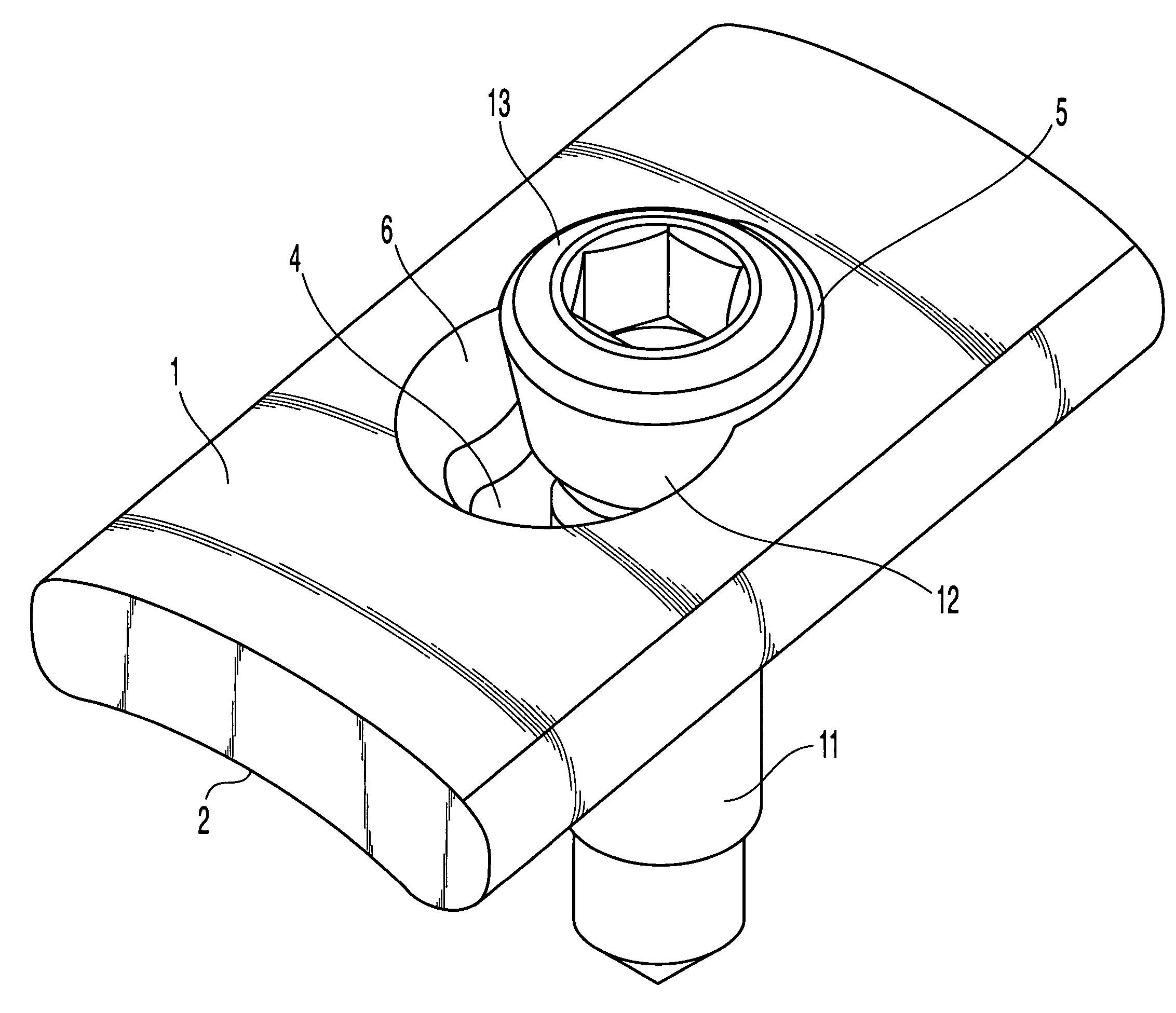
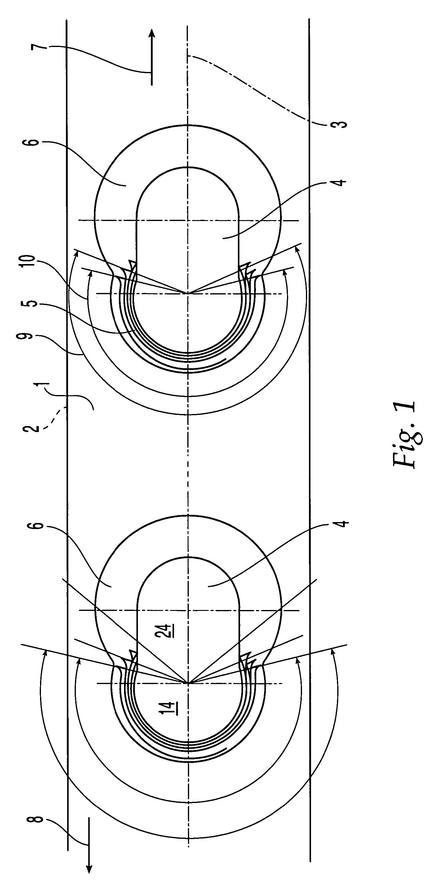
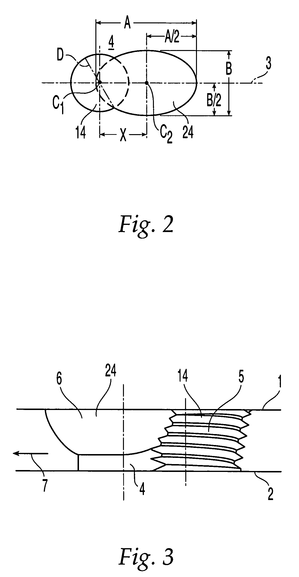
[0028]One embodiment of a bone plate according to the present invention is shown in FIG. 1. The bone plate defines a longitudinal axis 3, and includes an upper surface 1 and a bone contacting surface 2 intended for contact with the bone. At least one combination hole 4 extends through the upper surface 1 and the bone contacting surface 2. Hole 4 may receive a bone screw 11 that is used to hold the bone plate on the fractured bone. While two holes 4 are shown, the bone plate may be provided with any number of holes 4 as may be suitable for a specific surgical application. In addition, holes 4 may be disposed along the longitudinal axis 3 as shown in FIG. 2, however, holes 4 may alternatively be spaced from the longitudinal axis 3. One of ordinary skill in the art will know and appreciate that the bone plate may be provided with other types and configurations of holes in addition to combination hole 4. For example, the bone plate may be provided with substantially cylindrical holes, t...


PUM


Abstract

A bone plate includes an upper surface, a bone contacting surface, and at least one hole extending through the upper and bone contacting surfaces for receiving a bone screw. The at least one hole includes a first portion and a second portion that overlap one another. The first portion defines a substantially circular outer periphery and the second portion defines an elongated outer periphery that is elongated in a direction substantially parallel to the longitudinal axis of the plate. The first portion may have threads configured to engage threads on the head of a bone screw, and the second portion may be configured to cooperate with the head of a different bone screw to provide compression to the fracture.

Description

CROSS-REFERENCE TO RELATED APPLICATIONS[0001]The present application is a continuation of U.S. patent application Ser. No. 09 / 994,050, filed on Nov. 27, 2001, now U.S. Pat. No. 6,669,701, which is a continuation of the U.S. National Stage designation of International Application PCT / CH00 / 00037, filed Jan. 27, 2000. The entire contents of these applications is expressly incorporated herein by reference thereto.TECHNICAL FIELD OF THE INVENTION[0002]The present invention relates generally to devices for fixation of parts of a fractured bone and more specifically, to bone plates and systems for stabilization and / or compression of parts of a fractured bone.BACKGROUND OF THE INVENTION[0003]Bone plates may generally be utilized to carry out two different types of osteosynthesis, namely “rigid osteosynthesis” and “flexible osteosynthesis.” Rigid osteosynthesis is used for medical care of joint fractures, simple shaft fractures (where nailing is impossible) as well as for osteotomies. Aside ...

Claims


Application Information

Patent Timeline
IPC IPC(8): A61B17/56A61B17/00A61B17/58A61B17/80
CPCA61B17/8014A61B17/8052A61B17/8061A61B17/8057A61F2/28
Inventor FRIGG, ROBERT
Owner SYNTHES USA
Why Eureka
Try Eureka