Apparatus for locating a station initiating transmission of an emergency message in a network having multiple transmission sources

Inactive Publication Date: 2008-04-08
SHORETEL +1
View PDF14 Cites 8 Cited by
  • Summary
  • Abstract
  • Description
  • Claims
  • Application Information

AI Technical Summary

Benefits of technology

[0012]The unique code transmitted is used by the EMP to enter its data base which contains data correlating the exact location of every source with a unique code. This arrangement eliminates polling requirements of the prior art.

Problems solved by technology

Because of the variety of arrangements, protocols a

Method used


Image

  • Apparatus for locating a station initiating transmission of an emergency message in a network having multiple transmission sources
  • Apparatus for locating a station initiating transmission of an emergency message in a network having multiple transmission sources
  • Apparatus for locating a station initiating transmission of an emergency message in a network having multiple transmission sources

Examples


Embodiment Construction

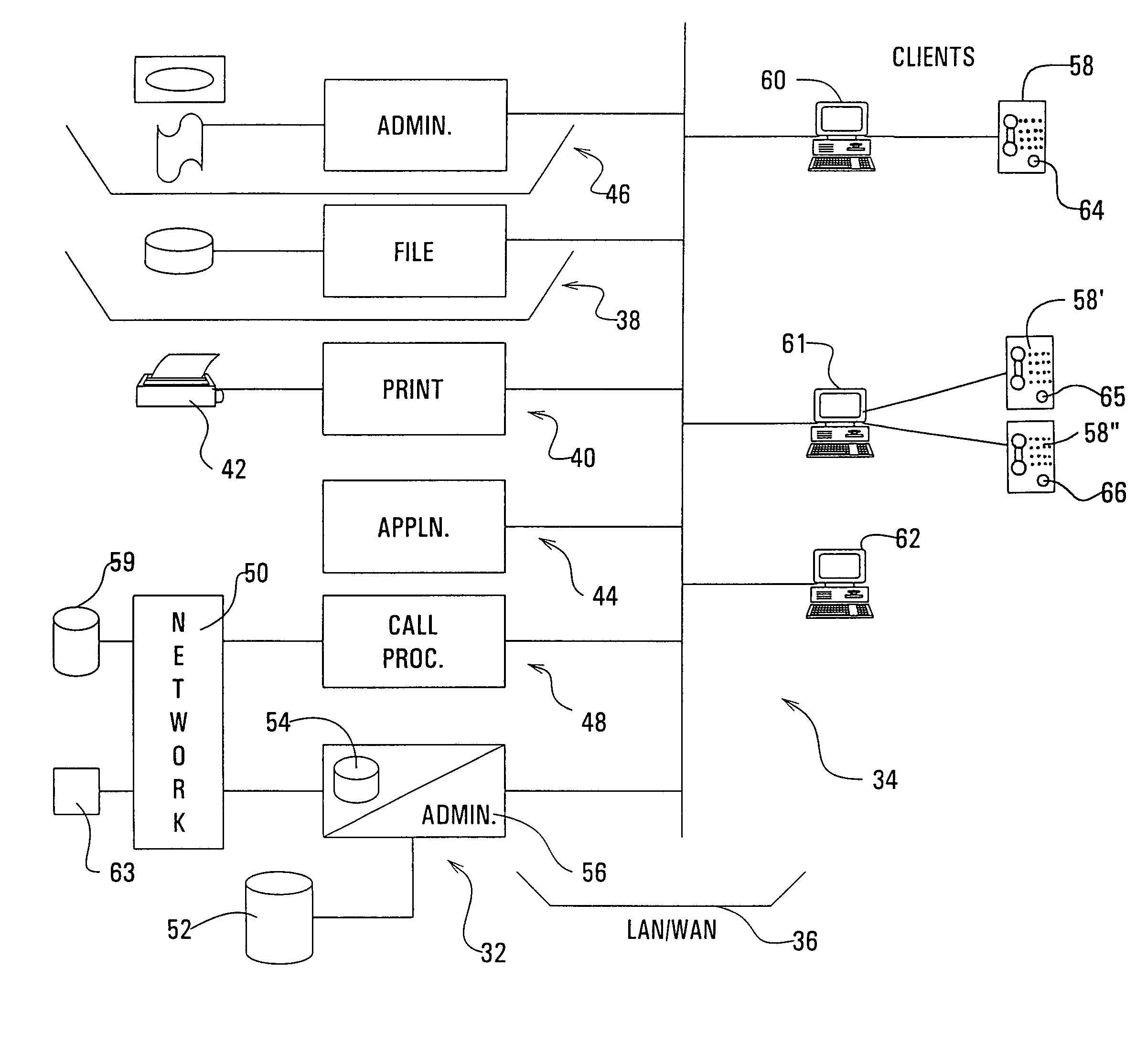
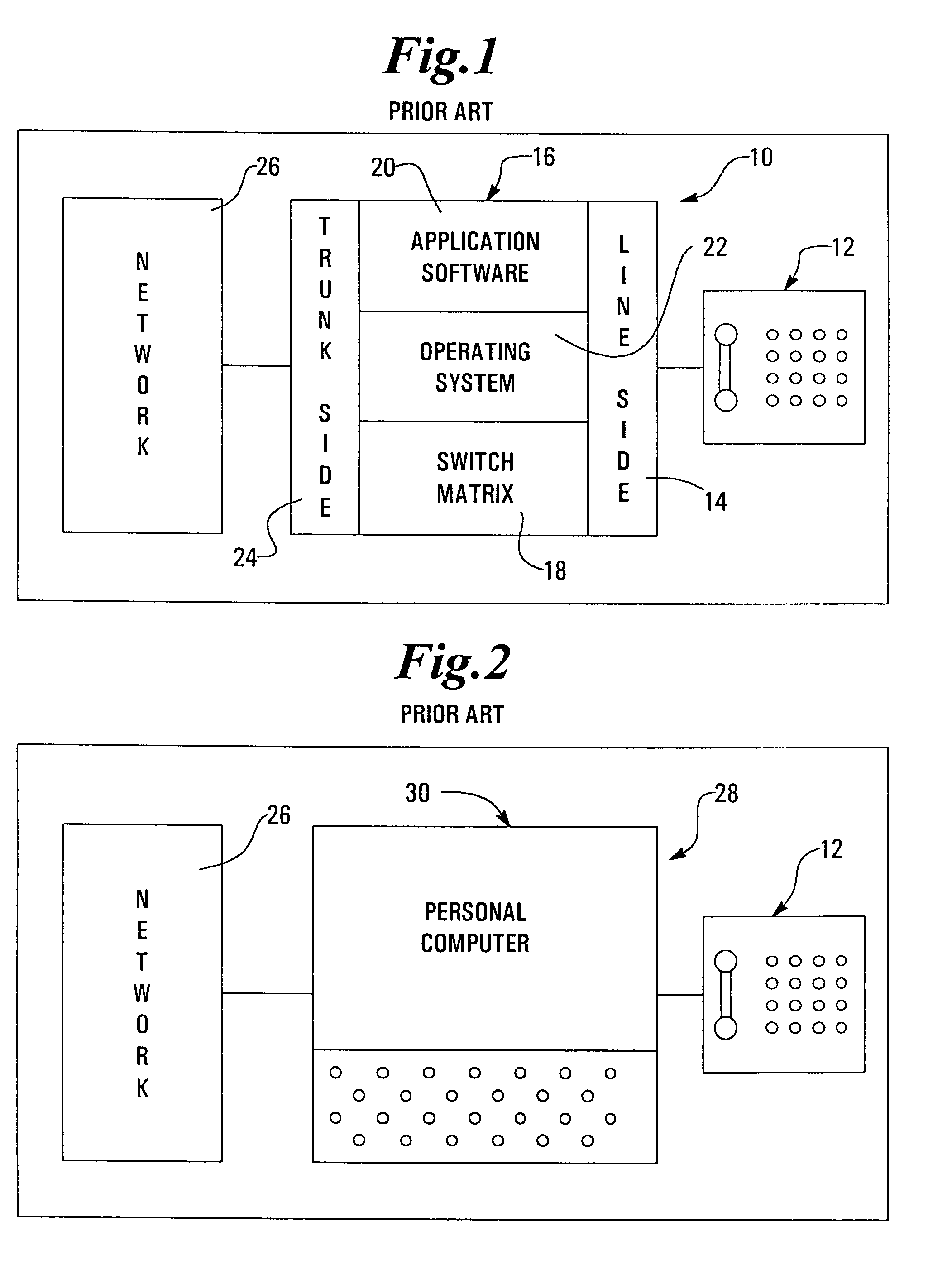
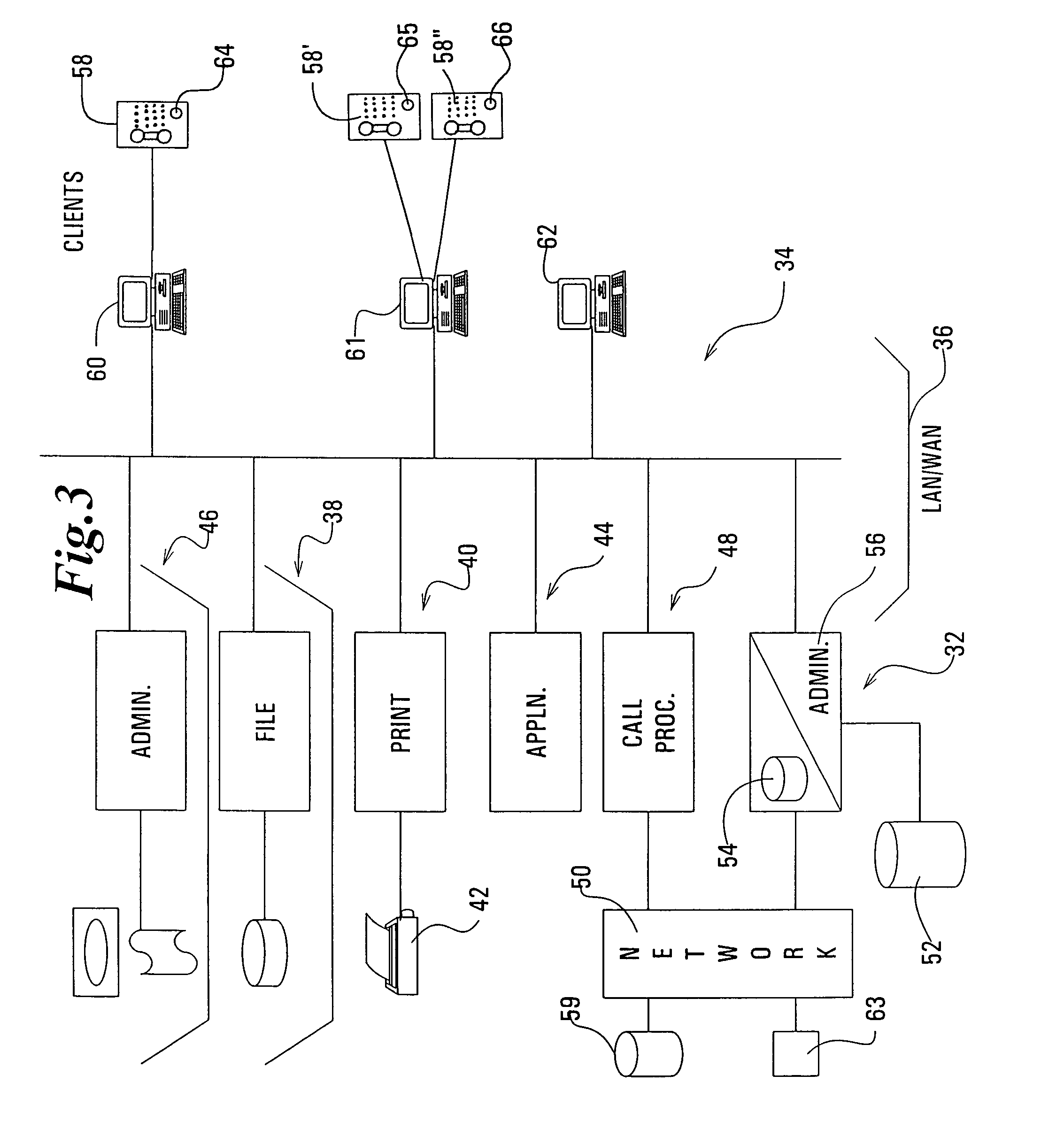
[0019]Referring now to the drawings, wherein like reference numerals denote like elements throughout the several views, FIG. 1 illustrates a telephony circuit 10 as known in the prior art. That figure illustrates a transmission point 12 such as a conventional telephone set that, for example, might be on an individual's desk at a particular facility. The transmission point 12 is on the line side 14 of a PBX 16 of a type characteristic in the prior art. The PBX 16 is made is made up of various hardware and software elements to effect switching. The PBX employs an operating system 22 to run the overall PBX apparatus 16. Other hardware / software elements that might be employed by a PBX 16 are a switch matrix 18 and application software modules 20. The application software 20 serves to implement special features of the PBX 16 that the owner or administrator has elected.

[0020]A side of the PBX 16 opposite that on which the telephone set 12 is located is known as the trunk side 24 of the PB...


PUM


Abstract

A system for identifying the location of an individual at a transmission source who has initiated a message relating to an emergency. The system includes means for determining the specific location of the message initiator.

Description

TECHNICAL FIELD[0001]The present invention deals broadly with the field of communications. More specifically, however it deals with the initiation of an emergency message and the determination of the location of a specific source of the emergency message so initiated. The specific focus of the invention is the determination of the precise location of a transmission source in a network having multiple transmission sources which has transmitted indicia defining the precise location, such as the floor and the specific location on the floor of a large multistory building or complex.BACKGROUND OF THE INVENTION[0002]The Internet system, for example, which now encompasses virtually the entire world with a network, provides means to communicate in a variety of ways including print, audio and video. In the past long distance communications between individuals was dominated by the telephone and its interconnecting networks. Today this role is being rapidly supplanted by communications over th...

Claims


Application Information

Patent Timeline
IPC IPC(8): H04M11/06H04M11/04
CPCH04M3/42357H04M11/04H04W4/02H04L67/18H04L29/12122H04L61/1547H04M3/42314H04M3/42323H04M7/006H04M2242/04H04L61/4547H04L67/52H04W4/029
Inventor MOODY, MARTIN D.
Owner SHORETEL
Why Eureka
Try Eureka