If the rails were superconducting, the preceding would be avoidable, but there would be technical issues in regards preventing
solid ice accumulation on rail surfaces.
Aside from the running surface difficulty presented by on rail ice,
moisture accretion within a
high voltage environment is less than desirable.
Short of effective sustained
dry gas purging or in vacuum applications, this would be unavoidable.
Radiation from intense arcing can produce
plasma ahead of the armature, which becomes a
self limiting problem in that induced
plasma serves to oppose armature acceleration as it represents a local, higher density gas component.
Radiation from intense arcing and typically associated with
plasma formation can produce / induce secondary plasma emission at some other location on the rail; this can close as a switch (commutate) resulting in a secondary arc and power leakage.
This is an additional complication and has the potential to ‘freeze’
metal onto the rail with each event, thus affecting subsequent launch attempts.
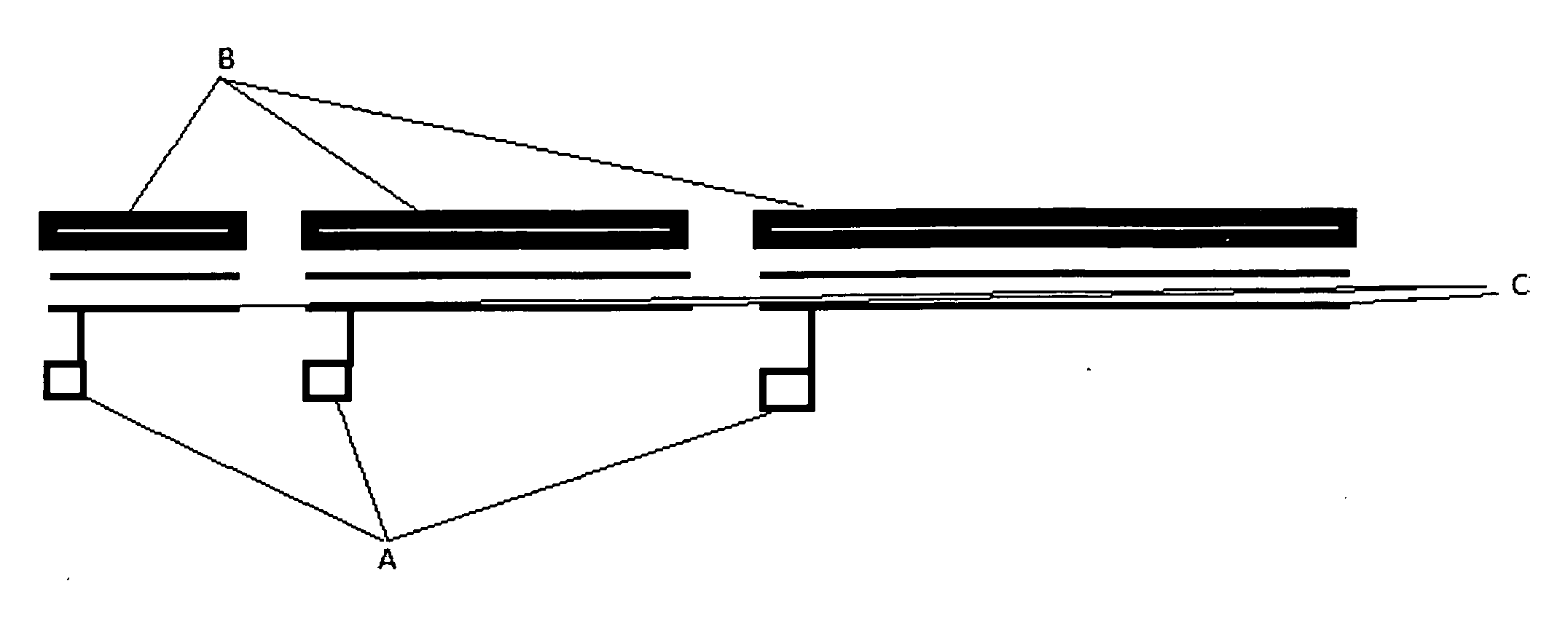
In the simple two rail configuration, given that the full drive current is channeled through the two parallel rails for the length of the
barrel (acceleration region), it is then a basic fact that, as armature moves from entrance to end of rail, the circuital self-
inductance increases commensurately, which complicates the issue of efficient power delivery to the armature.
As indicated, performance / efficiency and lifetime issues would be critical to any meaningful civilian application as distinct from military use.
However a more detailed evaluation of this concept shows that very high voltages could be needed to power the coils, so the concept may be unattractive for short barrels and
high velocity applications.
There are a number of deficiencies apparent with this approach.
This as alluded to in the statement that, high velocities may be unattractive with this concept.
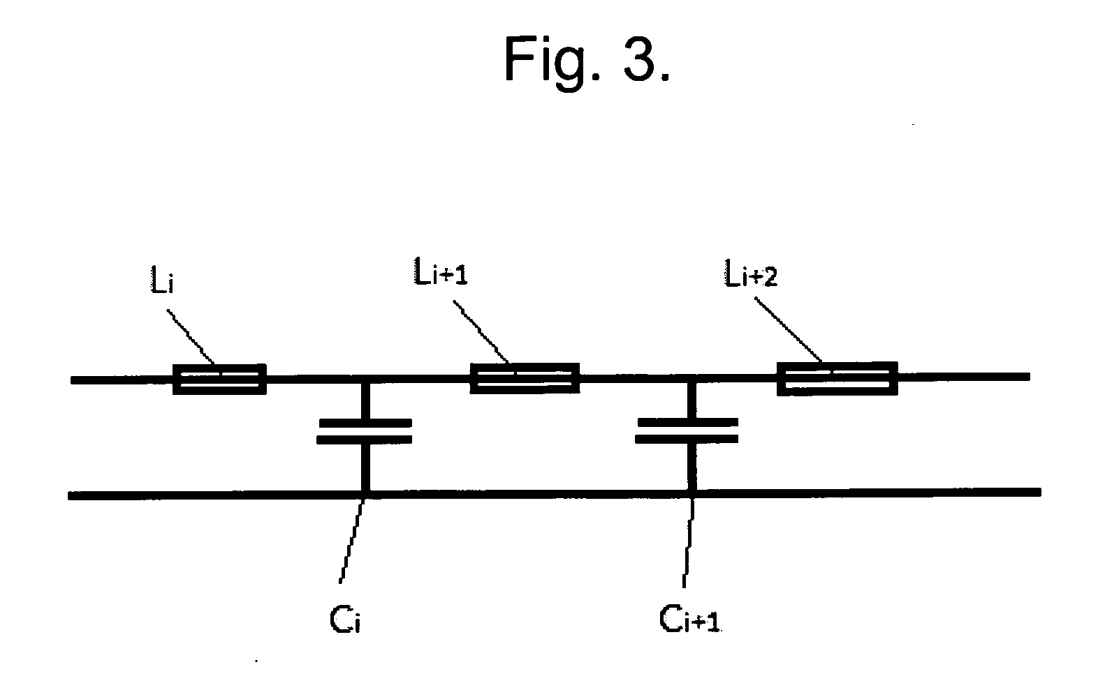
In addition, turning off the preceding coil precisely in
sync with the coil turned on is just as significant an issue if one wishes to avoid any growth in
system back
electromotive force (emf) or odd induced transients courtesy of flux accretion in the volume defined by a
common rail segment and armature.
The extension of this technology to the
muzzle velocities (>7500 m / s) and energies (>10 GJ) needed for direct launch of payloads into
orbit is very challenging, but may not be impossible.
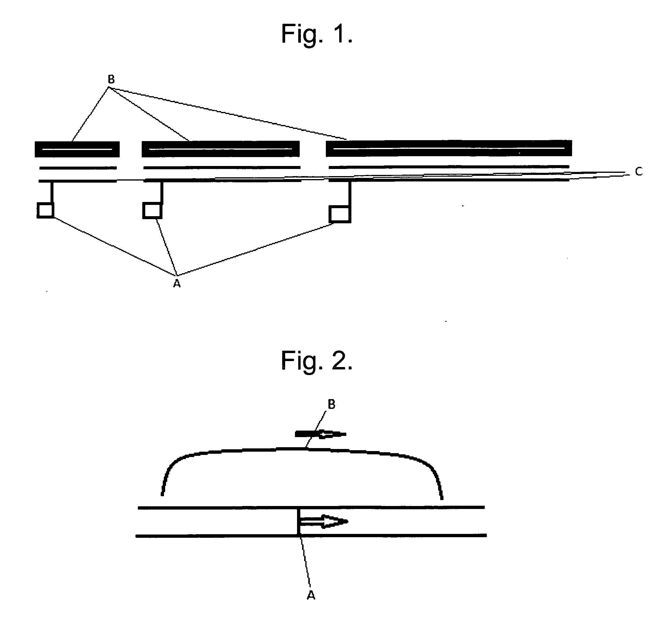
In other words, the system is in fact a series array of simple augmented railguns, in which case the local module is subject to the back emf problems associated with the local externally applied / augmented field armature interaction, as the turn off of the preceding module element's augmenting fields does not
counterpoint the turn on of the augmenting fields in any other separate module.
It is further apparent that within this technical approach, the externally applied
magnetic field will in general not be optimal within the duration of the armature acceleration event.
The latter may not be significant for small bore, moderate velocity systems, but will be significant to prohibitive at larger bore and higher velocities and thus presents a
scalability issue.
Finally, if the objective was to accelerate a
projectile to +20 km / s the switching and timing requirements and the associated voltages and currents of a sequenced individual coil series array would become severe.
This is no different to the problem presented by the coil switching issue in pure induction accelerators such as coil guns, where the
voltage required increases with velocity and thus
high voltage commutation of multiple coils in axial series represents the technological limit to achievable launch velocity.

