Air-fuel ratio controller for internal combustion engine

a technology of air-fuel ratio and air-fuel ratio, which is applied in the direction of electrical control, process and machine control, instruments, etc., can solve the problems of deteriorating state of air-fuel ratio control cylinder-by-cylinder, deterioration of estimation accuracy of air-fuel ratio of each cylinder, and inability to eliminate the variation among cylinders with reliability, etc., to achieve excellent calculation, suppress the effect of deterioration in calculation accuracy and high accuracy

Inactive Publication Date: 2008-04-15
DENSO CORP
View PDF11 Cites 18 Cited by
  • Summary
  • Abstract
  • Description
  • Claims
  • Application Information

AI Technical Summary

Benefits of technology

[0008]An object of the invention is to provide an air-fuel ratio controller for an internal combustion engine, capable of excellently calculating a cylinder-by-cylinder air-fuel ratio reflecting variations among cylinders, and accurately executing air-fuel ratio control on the basis of the cylinder-by-cylinder air-fuel ratio.
[0009]Another object of the invention is to provide an air-fuel ratio controller for an internal combustion engine, capable of correcting the air-fuel ratio detection timing of each cylinder to a proper direction in accordance with an air-fuel ratio and realizing improvement in accuracy of air-fuel ratio estimation of each cylinder.
[0011]It is considered that the response of the air-fuel ratio sensor varies between the case where a rich output is detected and the case where a lean output is detected and, generally, the response when a rich output is detected is higher. Consequently, by executing calculation of the cylinder-by-cylinder air-fuel ratio only when a rich output is detected, deterioration in the calculation accuracy can be suppressed, and the cylinder-by-cylinder air-fuel ratio can be excellently calculated reflecting variations among cylinders. Therefore, the air-fuel ratio control can be executed with high accuracy on the basis of the cylinder-by-cylinder air-fuel ratio. Even in the case of using an air-fuel ratio whose response is deteriorating, by using a rich sensor output having relatively high response, the cylinder-by-cylinder air-fuel ratio can be calculated excellently.
[0012]According to the invention, air-fuel ratio detection timing correcting means for correcting the air-fuel ratio detection timing in accordance with a target air-fuel ratio or a detected air-fuel ratio corrects the air-fuel ratio detection timing so as to be retarded with respect to the stoichiometric air-fuel ratio when the target air-fuel ratio or the detected air-fuel ratio is lean, and corrects the air-fuel ratio detection timing so as to be advanced with respect to the stoichiometric air-fuel ratio when the target air-fuel ratio or the detected air-fuel ratio is rich. In such a manner, the air-fuel ratio detection timing can be corrected to a proper direction in accordance with the air-fuel ratio (the target air-fuel ratio or detected air-fuel ratio). Thus, the accuracy of air-fuel ratio estimation of each cylinder can be improved.

Problems solved by technology

Therefore, a sensor output of high response and a sensor output of low response mixedly exist and a problem occurs such that variations among cylinders cannot be eliminated with reliability.
When the air-fuel ratio detection timing of each cylinder is deviated from the proper value, the estimation accuracy of the air-fuel ratio of each cylinder deteriorates, and the state of the cylinder-by-cylinder air-fuel ratio control deteriorates.

Method used


Image

  • Air-fuel ratio controller for internal combustion engine
  • Air-fuel ratio controller for internal combustion engine
  • Air-fuel ratio controller for internal combustion engine

Examples


first embodiment

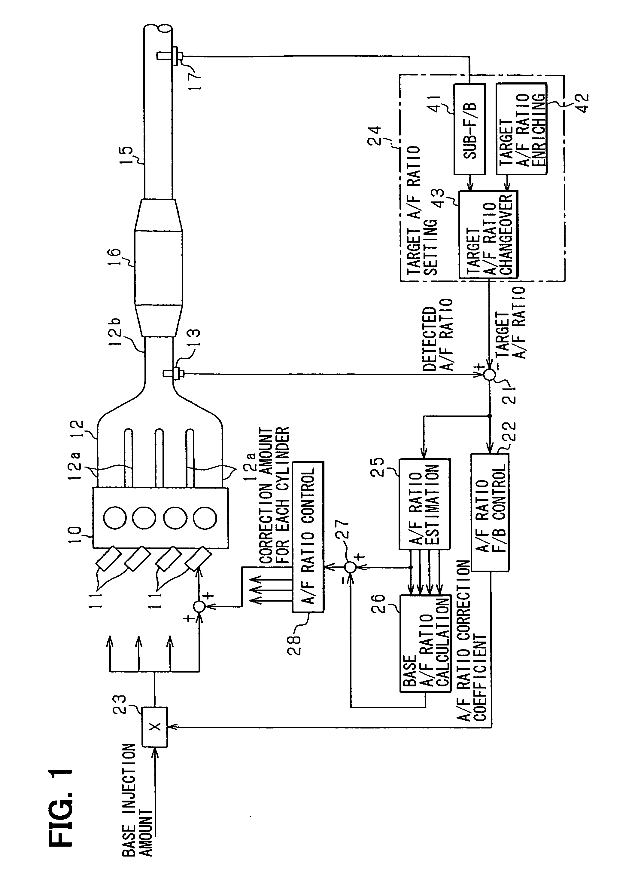
[0040]A first embodiment of the present invention will be described below with reference to the drawings. In the first embodiment, an engine control system is configured for an in-vehicle four-cylinder gasoline engine as a multi-cylinder internal combustion engine. In the control system, an electronic control unit for controlling an engine (hereinbelow, called engine ECU) is used as a center to perform a control on a fuel injection amount, a control on an ignition timing, and the like. First, the main components of the control system will be described with reference to FIG. 1.

[0041]In FIG. 1, an electromagnetically driven fuel injection valve 11 is attached to each of cylinders near intake ports of an engine 10. When a fuel is injected and supplied from the fuel injection valve 11 to the engine 10, the fuel injected by the fuel injection valve 11 is mixed with an intake air in the intake port of each cylinder, thereby generating air-fuel mixture. The air-fuel mixture is introduced i...

second embodiment

[0091]Next, a second embodiment will be described mainly with respect to the points different from the foregoing first embodiment. In the second embodiment, at the time of calculating the cylinder-by-cylinder air-fuel ratio, the response of the air-fuel ratio sensor 13 is detected and, on the basis of the detection result, the target air-fuel ratio is set.

[0092]FIG. 8 is a diagram showing an outline of an engine control system in the second embodiment. In FIG. 8, as the point different from FIG. 1, a sensor response detection part 51 is provided, and the response of the air-fuel ratio sensor 13 is detected by the sensor response detection part 51. In the sensor response detection part 51, lapse time (response time) until a predetermined response change appears when the target air-fuel ratio is changed step by step is measured and, on the basis of the lapse time, whether the sensor response is fast or slow is determined. The target air-fuel ratio changeover part 43 changes the target...

third embodiment

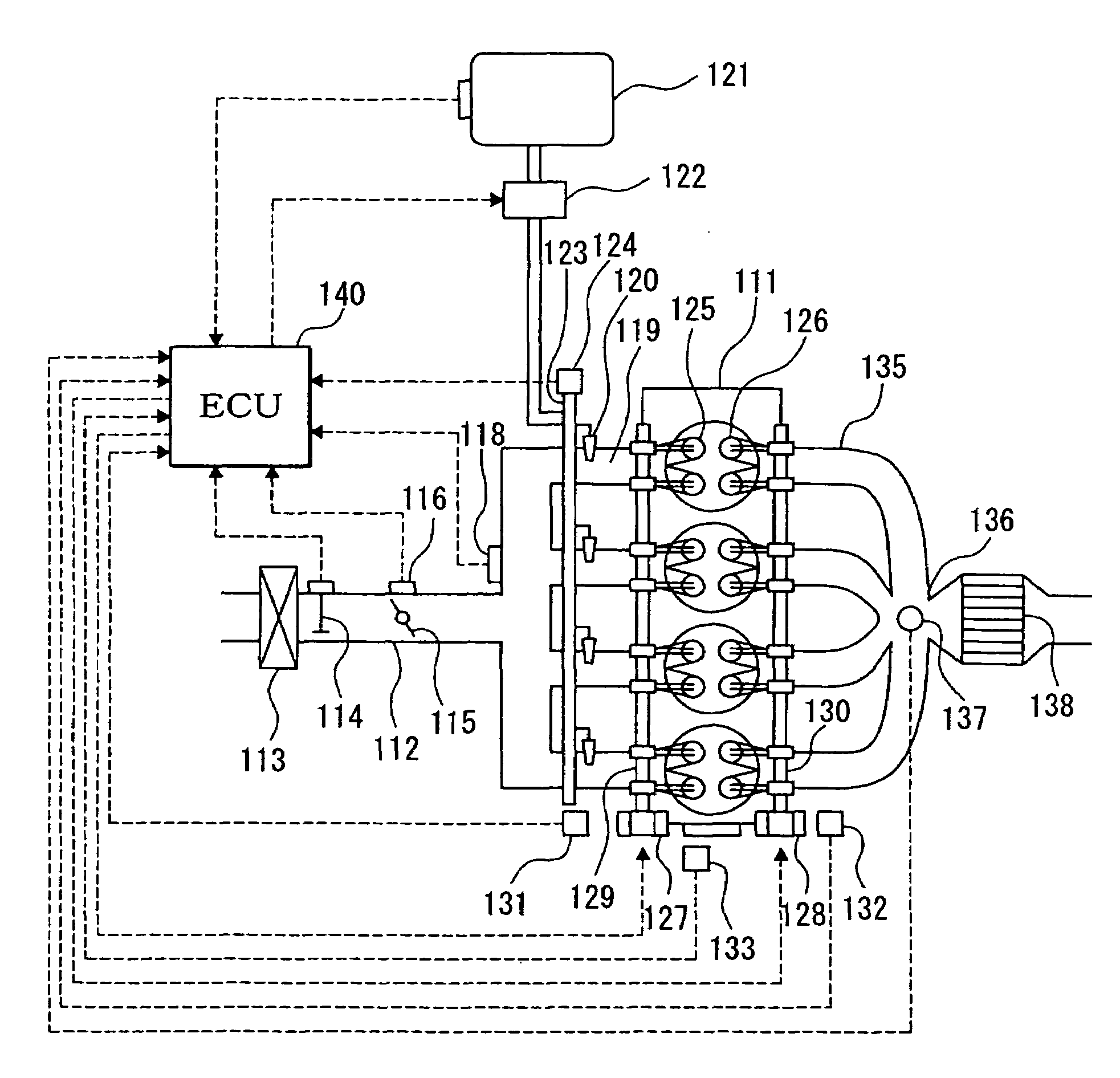
[0119]A third embodiment of the invention will be described with reference to FIGS. 12 to 18. Referring first to FIG. 12, a schematic configuration of a whole engine control system will be described. An air cleaner 113 is provided at the most upstream position of an intake pipe 112 of an in-line four-cylinder engine 111 as an internal combustion engine. An air flow meter 114 for detecting an intake air volume is provided downstream of the air cleaner 113. A throttle valve 115 whose opening is adjusted by a motor or the like and a throttle opening sensor 116 for detecting a throttle opening are provided downstream of the air flow meter 114.

[0120]Further, a surge tank 117 is provided downstream of the throttle valve 115. The surge tank 17 is provided with an intake manifold pressure sensor 118 for detecting an intake manifold pressure. The surge tank 17 is also provided with an intake manifold 119 for introducing air into the cylinders of the engine 111. A fuel injection valve 120 for...


PUM


Abstract

A target air-fuel ratio setting part has a sub-feedback part, a target air-fuel ratio enriching part, and a target air-fuel ratio changeover part. The sub-feedback part variably sets a target air-fuel ratio upstream of a catalyst on the basis of a detection signal of an O2 sensor provided downstream of the catalyst. The target air-fuel ratio changeover part uses, as the target air-fuel ratio, a rich target air-fuel ratio which is set by the target air-fuel ratio enriching part on conditions such that the target air-fuel ratio set by the sub-feedback part is rich. A cylinder-by-cylinder air-fuel ratio estimation part calculates a cylinder-by-cylinder air-fuel ratio on the basis of a detection value of an air-fuel ratio sensor and the target air-fuel ratio.

Description

CROSS-REFERENCE TO RELATED APPLICATION[0001]This application is based on Japanese Patent Applications No. 2005-208140 filed on Jul. 19, 2005, and No. 2006-29811 filed on Feb. 7, 2006, the disclosure of which are incorporated herein by reference.FIELD OF THE INVENTION[0002]The present invention relates to a cylinder-by-cylinder air-fuel ratio controller for an internal combustion engine, for controlling the air-fuel ratio of each cylinder on the basis of a detection value of one air-fuel ratio sensor installed in an exhaust collection part in an internal combustion engine.BACKGROUND OF THE INVENTION[0003]JP-8-338285A (U.S. Pat. No. 5,730,111) discloses a technique in which, to improve air-fuel ratio control accuracy by reducing variations in the air-fuel ratio among cylinders of an internal combustion engine, at the time of performing air-fuel ratio detection by an air-fuel ratio sensor, a cylinder from which an exhaust to be actually detected came is specified and a feedback control...

Claims


Application Information

Patent Timeline
Patent Type & Authority Patents(United States)
IPC IPC(8): F02D41/14
CPCF02D41/008F02D41/1401F02D41/1441F02D41/1458F02D2041/1419
Inventor HIRATA, YASUOOKAMOTO, AKIHIROWAKAHARA, KEIJI
Owner DENSO CORP
Why Eureka
Try Eureka