System and method for coherently combining a plurality of radars

a plurality of radars and coherent technology, applied in the field of radar systems and methods, can solve the problems of inaccuracy measurement, long and expensive process of new radar design, and use of existing radars, and achieve the effect of improving signal gain and improving signal gain

Active Publication Date: 2008-04-15
RAYTHEON CO
View PDF35 Cites 19 Cited by
  • Summary
  • Abstract
  • Description
  • Claims
  • Application Information

AI Technical Summary

Benefits of technology

[0012]In accordance with the present invention, a method of calibrating a plurality of radars includes selecting a reference radar from among the plurality of radars, and selecting one or more pairs of radars, each one of the pairs of radars including the reference radar and a respective paired radar from among the plurality of radars. The method also includes generating calibration values associated with the reference radar and with the paired radar and generating initialization values associated with the reference radar and with the paired radar. The method still further includes transmitting an adjusted signal with the paired radar and an unadjusted signal with the reference radar, the adjusted signal generated in accordance with the initialization values and the calibration values. A first composite signal is received with the reference radar and a second composite signal is received with the paired radar, which are associated with the adjusted signal and the unadjusted signal. The method coherently sums the first composite signals and second composite signal to provide a cohered signal. With this particular arrangement, the method can cohere the plurality of radars to provide improved signal gain.
[0013]In accordance with another aspect of the present invention, an apparatus for calibrating a plurality of radars includes an association processor for associating at least one respective target track provided by each of a pair of radars from among the plurality of radars including a reference radar and a paired radar. The apparatus also includes a calibration processor coupled to the association processor for providing calibration values associated with the pair of radars, an initialization processor coupled to the calibration processor for providing initialization values associated with the pair of radars, and a coherence maintenance processor coupled to the initialization processor to adjust at least one of a first signal transmitted by the reference radar and a second signal transmitted by the paired radar in accordance with the initialization values and with the calibration values, and to coherently sum a first composite signal received by the reference radar with a second composite signal received by the paired radar. With this particular arrangement, the apparatus can cohere the plurality of radars providing improved signal gain.

Problems solved by technology

Redesign of a new radar is a very long and expensive process and makes no use of existing radars.
However, it is generally not sufficient that the position of the radar antennas merely be mechanically measured, since the distance between the radar antennas can be quite large compared to a wavelength, resulting in measurement inaccuracy.
Furthermore, knowing only the mechanical separation between the radars is not sufficient since it does not account for internal electrical differences in time delay or phase shift between radars.
Measurement of mechanical separation also does not account for a change in these electrical parameters with time due to temperature changes, aging, parts replacement, etc.
However, mobile radars are subject to changes in relative position much greater than a wavelength, and therefore, calibration of relative position of mobile radar antennas would have to be performed each time the mobile radars are moved.
One of ordinary skill in the art will understand that calibrating the relative positions of a plurality of radar arrays is difficult and subject to increasing errors as the separation of the plurality of radar antennas increases.
However, the monostatic and bistatic target echoes received by each radar generally appear at different ranges (time delays) and with different phases, and therefore, do not generally sum coherently with no phase difference.

Method used


Image

  • System and method for coherently combining a plurality of radars
  • System and method for coherently combining a plurality of radars
  • System and method for coherently combining a plurality of radars

Examples


Embodiment Construction

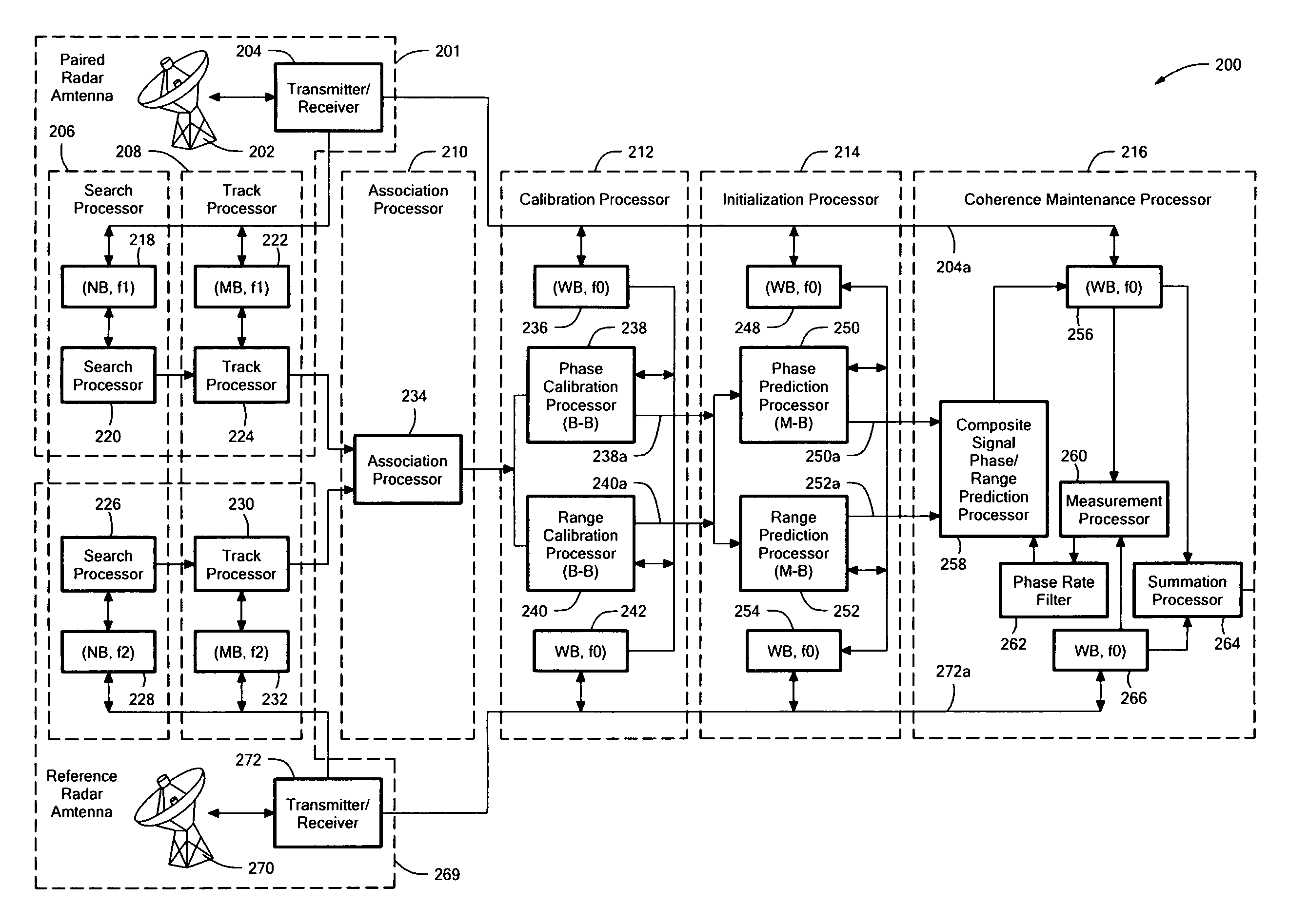
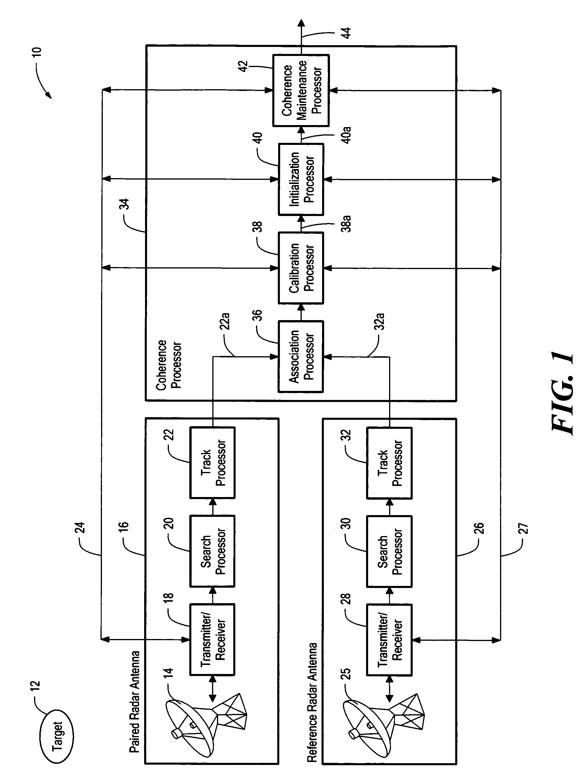
[0030]Before describing the system and method of the present invention, some introductory concepts and terminology are explained. As used herein, the term “reference radar” is used to describe one radar selected from among a group of two or more radars. As used herein, the term “paired radar” is used to describe any radar other than the reference radar selected from among the group of two or more radars.

[0031]While much of the discussion below describes but one paired radar, it should be appreciated that there can be any number of paired radars, and the same apparatus and methods described below can apply to each paired radar. The reference radar and the paired radar described below can be different types of radars. The paired radar is sometimes referred to herein as “radar 1” and the reference radar is sometimes referred to herein as “radar 2.”

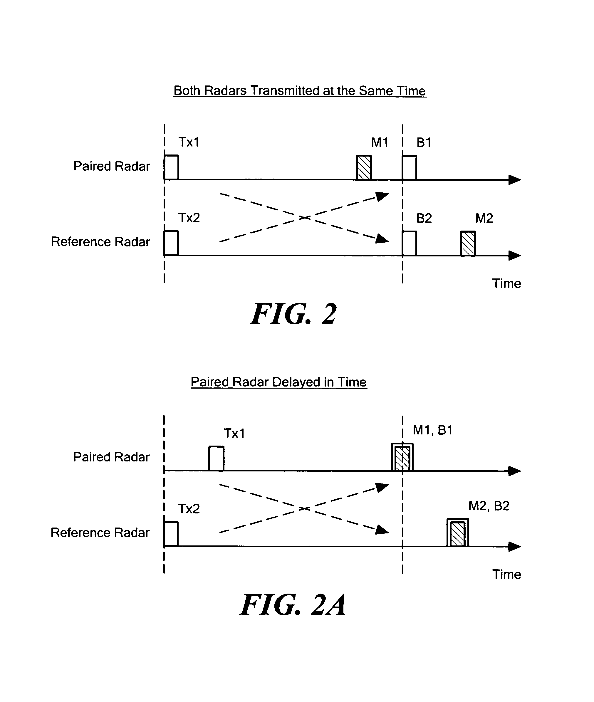
[0032]As used herein, the terms “range” and “time delay” are sometimes used synonymously. One of ordinary skill in the art will understand t...


PUM


Abstract

Systems and techniques for coherent combining radars include generating a phase and range calibration and initialization values for adjusting a time delay and a phase of a transmitted pulse from one of the radars, resulting in received composite target echoes at each of the radars having contributions from monostatic and bistatic echoes. The method further includes predicting phase and range correction values for further adjusting the time delay and the phase of subsequent radar pulses transmitted by one of the radars to continue to result in received composite target echoes at each of the radars. The method further includes coherently summing the composite target echoes.

Description

CROSS REFERENCE TO RELATED APPLICATIONS[0001]This application claims the benefit under 35 U.S.C. §119(e) of U.S. Provisional Application No. 60 / 668,137 filed Apr. 4, 2005, which application is incorporated herein by reference in its entirety.STATEMENT REGARDING FEDERALLY SPONSORED RESEARCH[0002]Not Applicable.FIELD OF THE INVENTION[0003]This invention relates generally to radar systems and methods, and, more particularly, to a system and method for coherently combining a plurality of radars.BACKGROUND OF THE INVENTION[0004]As is known, a single radar has a theoretical maximum signal to noise ratio (SNR) for a given size target at given range. The signal to noise ratio directly affects the ability of the radar to detect, track, and identify the target. The maximum signal to noise ratio is determined by a variety of radar characteristics, including but not limited to, the size of the radar antenna, the radar transmit power, and the radar receiver noise level. Each of these radar chara...

Claims


Application Information

Patent Timeline
Patent Type & Authority Patents(United States)
IPC IPC(8): G01S7/40G01S13/00
CPCG01S7/288G01S7/40G01S7/42G01S13/003G01S13/87G01S2013/9058G01S13/9058
Inventor THOME, GEORGE D.ENZMANN, ROBERT P.STEUDEL, FRITZ
Owner RAYTHEON CO
Why Eureka
Try Eureka