
Document feeder and image reading apparatus with the same

a document feeder and image reading technology, applied in the direction of instruments, electrographic processes, transportation and packaging, etc., can solve the problems of deteriorating image quality, difficult to automatically feed an original for other purposes, etc., to prevent deterioration of image quality, reduce damage and transportation troubles, and minimize the effect of transporting path

Inactive Publication Date: 2008-04-15
NISCA KK
View PDF5 Cites 8 Cited by
  • Summary
  • Abstract
  • Description
  • Claims
  • Application Information

AI Technical Summary

Benefits of technology

[0013]According to the present invention, the frame with the transporting belt may be provided with a transporting mechanism such as a vacuum device. The frame may be provided with the vertical positioning member for abutting against the platen surface to determine a vertical position. With this configuration, it is possible to properly arrange the transporting belt and vacuum device on the platen, thereby transporting the original reliably.
[0015]According to the present invention, an original setting reference such as a step may be provided at a flange portion around the platen, and the device frame is installed on the platen. The transporting belt for transporting the original along the platen is mounted on the device frame. The device frame is provided with an original stopper for stopping the original, and positioning means for setting positions of the original stopper and the original setting reference. The original stopper is disposed at a location away from the original setting reference. Accordingly, the original transported by the transporting belt is stopped and set at a location closer to the center of the platen from an edge end portion thereof, thereby preventing deterioration of image quality due to leakage of light upon exposure.
[0016]According to the present invention, the original stopper may be movable to a plurality of locations according to a longitudinal size of the original on the platen. Accordingly, it is possible to minimize a transporting path, thereby reducing damage and transportation troubles. The image reading device performs several operation modes including an operation mode of starting to read from the original setting reference and an operation mode of starting to read from the original stopper position. Accordingly, it is possible to read an image from a proper location. The operation modes can be selected through input means, detecting means such as a sensor for detecting whether the transporting belt is located on the platen, or determining means for determining whether a control circuit of the transporting belt is electrically connected to a control circuit of photoelectric converting means.
[0017]According to the present invention, the document feeder is arranged to feed a small-size original including a photograph. The device frame covers the platen and is provided with the transporting case frame covering a part of the platen. The transporting case frame is provided with the transporting belt and the original stopper. The device frame is provided with an installing member for abutting against the original setting reference on the platen. Accordingly, the small document feeder is mounted on the platen, and the device frame covers the entire portion of the platen to prevent light leakage during exposure.

Problems solved by technology

When a feeding device capable of feeding a special original including a photograph is integrally installed on a reading platen of a copying machine, scanner, and the like, it is difficult to automatically feed an original for other purpose, which is undesirable.
On the other hand, in a feeding device, if the stopper for stopping the original is located at the manual setting reference, since the manual setting reference is located at an edge portion of the platen, light from a light source leaks outside, thereby deteriorating image quality.

Method used


Image

  • Document feeder and image reading apparatus with the same
  • Document feeder and image reading apparatus with the same
  • Document feeder and image reading apparatus with the same

Examples


Embodiment Construction

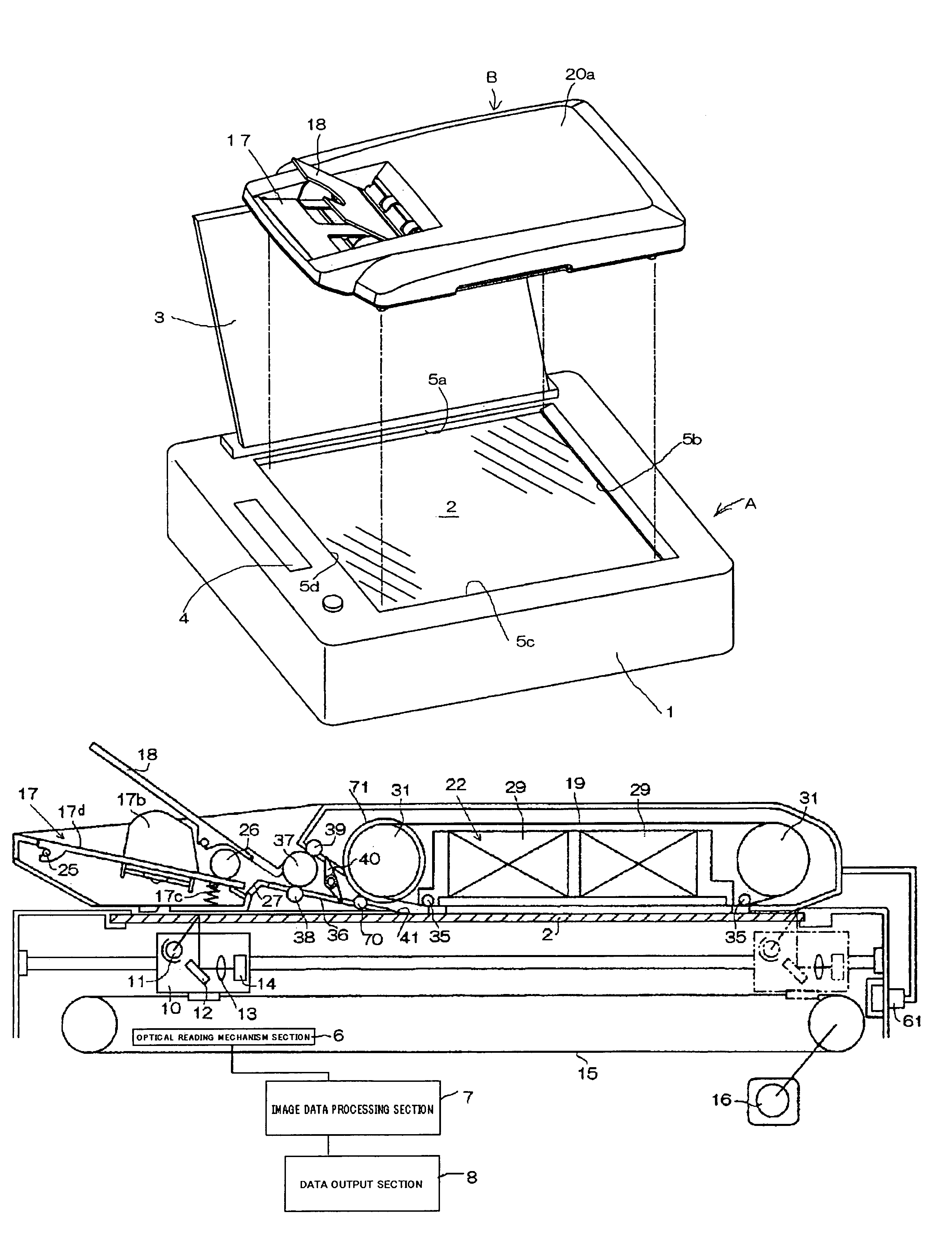
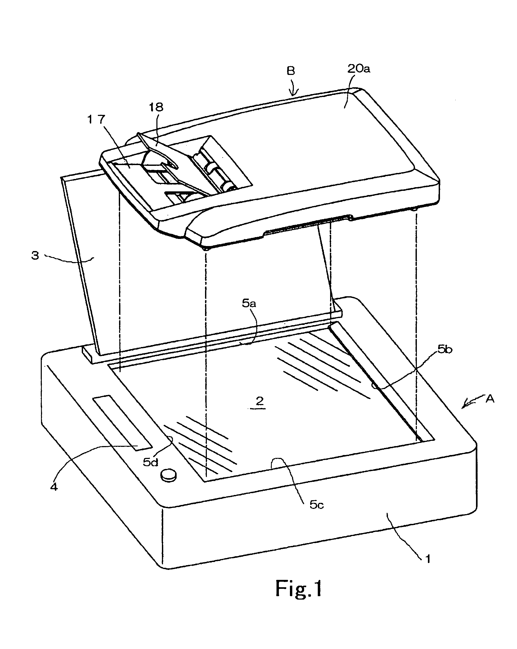
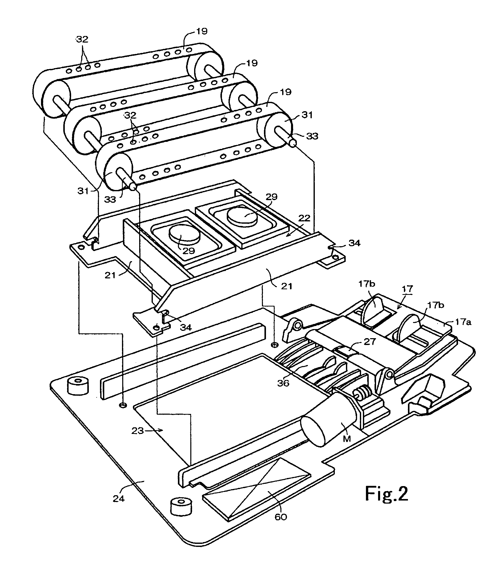
[0031]Hereunder, embodiments of the present invention will be explained with reference to the accompanying drawings. FIG. 1 is a perspective view showing a document feeder mounted on a scanner device; FIG. 2 is an exploded perspective view of the feeding device shown in FIG. 1; FIG. 3 is a cross-sectional view of the feeding device shown in FIG. 2; FIG. 4 is a bottom view of the feeding device shown in FIG. 2; and FIG. 5 is a bottom view of a transporting unit constituting a part of the feeding device shown in FIG. 2.

[0032]As shown in FIG. 1, a feeding device B is installed above a platen 2 of an image reading apparatus A such as a scanner device. In the image reading apparatus A, the platen 2 is provided on a part of a casing 1. The platen 2 is formed of a transparent and flat glass plate so as to place an original on a top surface thereof.

[0033]The casing 1 is provided with a flange 5 having a step 5a for fixing the platen 2 and abutting against an original thereby to restrict a s...


PUM


Abstract

A document feeder includes a frame to be disposed on a platen of a scanner; a sheet feeding stacker, a discharge stacker, and a transporting belt mounted on the frame; a lateral positioning member mounted on the frame for restricting the transporting belt laterally; and a vertical positioning member mounted on the frame for restricting the transportation belt vertically. The lateral positioning member is composed of a projection for abutting against a flange portion provided at a peripheral side of the platen to laterally restrict a position of the transporting belt. The vertical positioning member is composed of a projection for abutting against a surface of the platen to vertically restrict the position of the transporting belt.

Description

BACKGROUND OF THE INVENTION AND RELATED ART STATEMENT[0001]The present invention relates to a document feeder for feeding an original to an image reading platen in an image reading device such as a copy machine, a printer, a scanner, and a facsimile machine, and for storing the originals after reading the original. The present invention also relates to an image reading apparatus with the document feeder.[0002]In general, there have been various feeding devices for automatically feeding and placing an original from a sheet feed stacker to an image reading platen in a scanner. A conventional feeding device is mounted on an upper portion of the platen of the image reading apparatus using a hinge so that the feeding device can be freely opened and closed. When the feeding device is not used for reading an original, an operator opens the feeding device to place the original on the platen manually and then covers the platen with the feeding device.[0003]Recently, a copy machine, a scanner...

Claims


Application Information

Patent Timeline
Patent Type & Authority Patents(United States)
IPC IPC(8): H04N1/04G03G15/00H04N1/21B65H5/22B65H9/10
CPCB65H5/224B65H9/101B65H2406/323
Inventor OOMORI, MASAKISHIMIZU, MAKOTOSHIINA, TOSHIHITOJINZA, OSAMU
Owner NISCA KK
Learn More