Airborne free space optical communication apparatus and method with subcarrier multiplexing

an optical communication apparatus and free space technology, applied in the field of high-speed communication, can solve the problems of system data rates of the order of 1 gbps, and achieve the effect of reducing distortion and improving link performan

Active Publication Date: 2008-04-15
L3 TECH INC
View PDF3 Cites 10 Cited by
  • Summary
  • Abstract
  • Description
  • Claims
  • Application Information

AI Technical Summary

Benefits of technology

[0018]Filters may be used in the laser terminal to assure proper wavelength, eliminate unwanted portions of the waveform, or to perform other tasks. The modulated optical signal is then amplified, using an optical amplifier (such as an erbium doped fiber amplifier (EDFA), or other device).
[0022]The optical receiver may include adaptive optics, or other devices, to mitigate distortions encountered in the free-space channel. These distortion mitigation devices may or may not utilize information provided by the remote transmitter. The pointing and tracking of the receive optical terminal may rely on the pointing and tracking of the transmit optical terminal, or may be performed independently.
[0023]The aggregate RF signal is demultiplexed, to separate the individual RF subcarrier channels, and downconverted to the proper intermediate frequency (IF). The individual IF signals are amplified, using a low-noise amplifier, to improve link performance. An automatic gain control (AGC) device may be employed to adjust the power level of each IF signal.

Problems solved by technology

However, due to RF frequency band limitations (imposed by the U.S. and other governments), such systems are limited to data rates on the order of 1 Gbps.

Method used


Image

  • Airborne free space optical communication apparatus and method with subcarrier multiplexing
  • Airborne free space optical communication apparatus and method with subcarrier multiplexing
  • Airborne free space optical communication apparatus and method with subcarrier multiplexing

Examples


Embodiment Construction

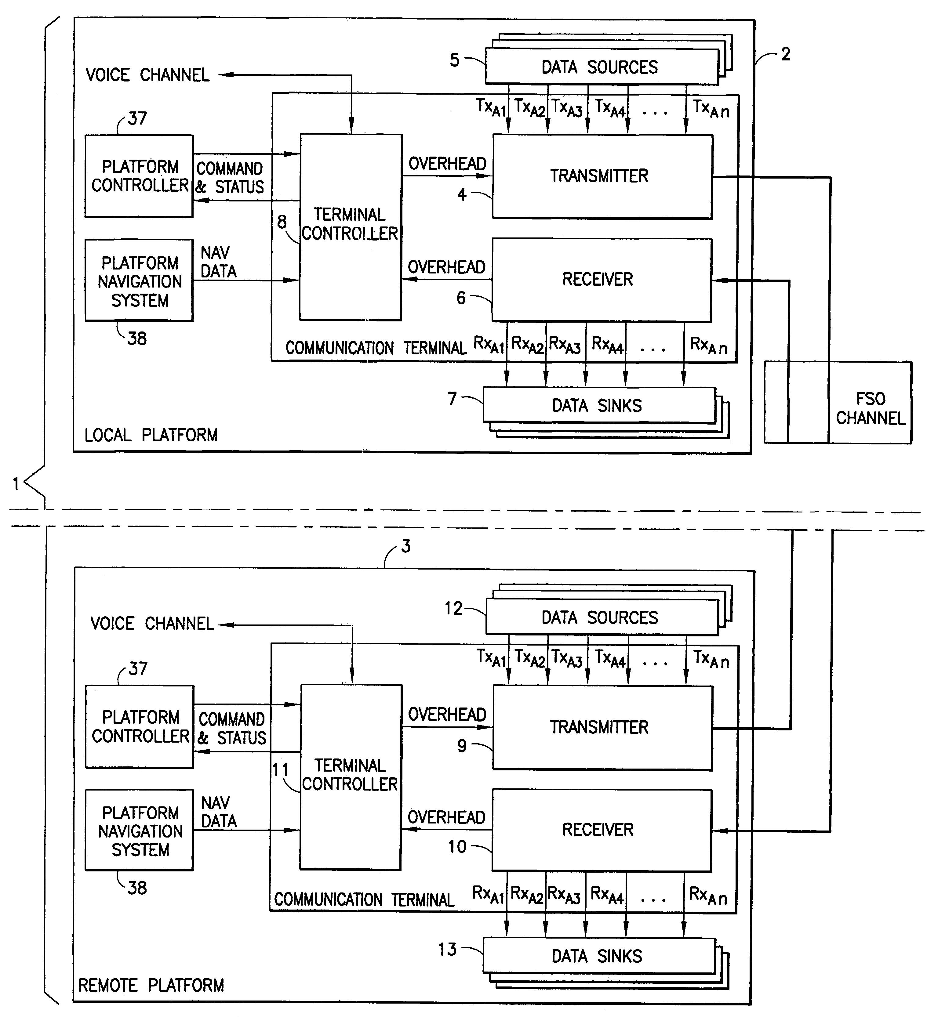
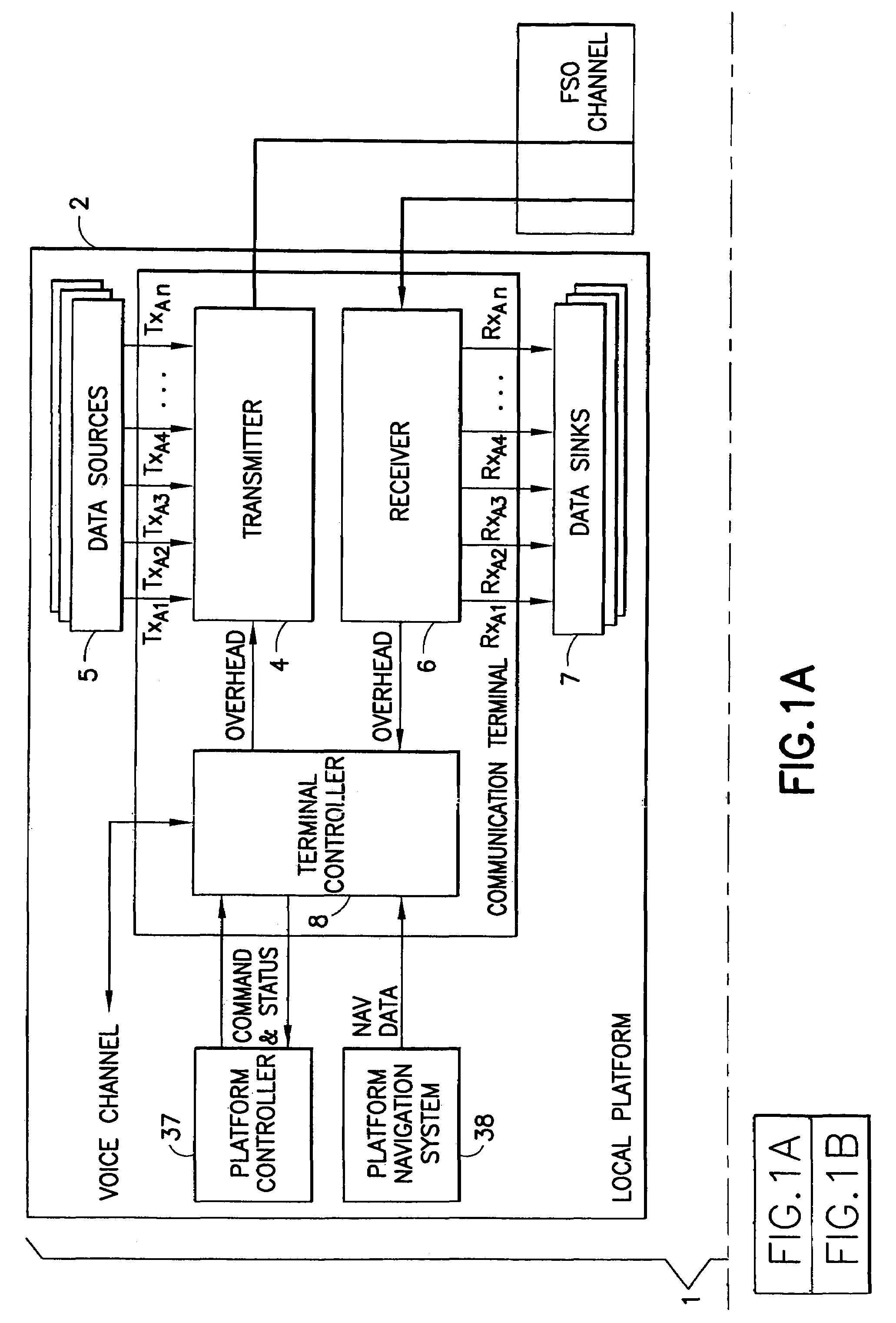
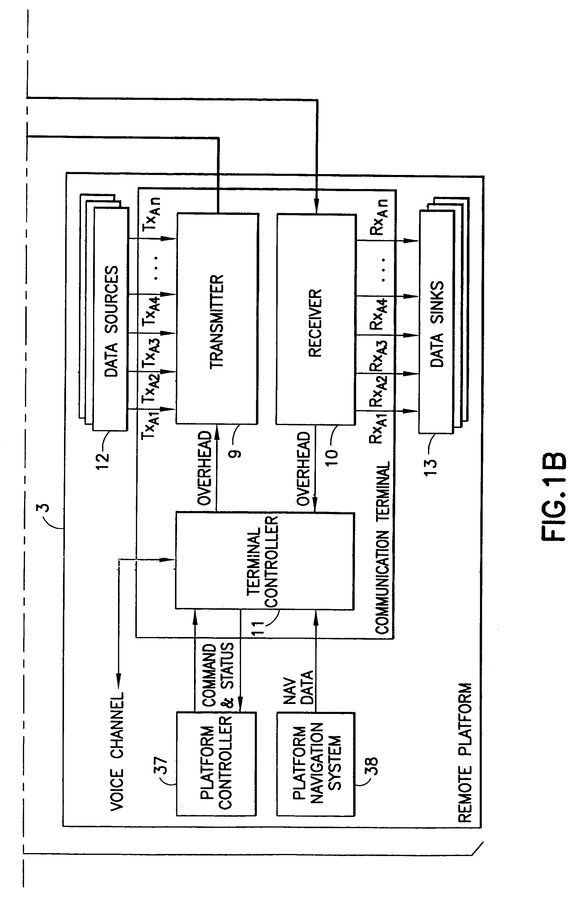
[0035]A communication system 1 is shown in FIG. 1 and consists of communication terminals 2 and 3 which are located remote from one another. The terminals 2 and 3 are placed on platforms that are generally moving with respect to each other, for example, an aircraft and ground station, satellite, or other aircraft (not shown) Terminal 2 consists of a transmitter module 4 that includes means to receive and process data from data sources 5. In addition terminal 2 is constructed having receiver 6 that includes means to receive, process and deliver data to data memory 7. Terminal controller 8 contains the necessary computer functions to maintain and operate the terminal 2. Terminal 3 is identical to terminal 2 and includes transmitter 9, receiver 10, and terminal controller 11 for performing the same functions at communication terminal 3. Data sources 12 and data memory 13 provide and retain data for transmission or after reception.

[0036]The transmitter modules 4 and 9 are shown in FIG. ...


PUM


Abstract

A free space laser communication system uses subcarrier multiplexing to prepare multiple data communication channels for impressing onto a laser carrier. Sending and receiving terminals mutually track to insure acquisition of the transmitted data signals.

Description

BACKGROUND OF THE INVENTION[0001]1. Field of the Invention[0002]The present invention relates to high-speed communication between two aircraft, between an aircraft and a ground facility, or between an aircraft and a satellite. More particularly, the invention relates to the use of apparatus to employ subcarrier multiplexing techniques to modulate and demodulate an optical signal, transmitted between the two entities (transmitter and receiver) in free space.[0003]2. Brief Description of Related Developments[0004]Airborne communication systems currently employ radio-frequency (RF) transmission techniques to transmit information in free space. However, due to RF frequency band limitations (imposed by the U.S. and other governments), such systems are limited to data rates on the order of 1 Gbps.[0005]Demands for higher transmission rates are increasing. Free-space optical (FSO) techniques, in which an optical signal (produced by a laser, for example) is used to carry the information, of...

Claims


Application Information

Patent Timeline
Patent Type & Authority Patents(United States)
IPC IPC(8): H04B10/00H04B10/10H04B10/118H04B10/22
CPCH04B10/1127H04B10/118H04B10/22H04B7/18506H04B7/18508
Inventor WOLCOTT, THEODORE J.HARRIS, JOHNNY M.ERTEL, RICHARD B.
Owner L3 TECH INC
Why Eureka
Try Eureka