Thermoelectric heat pumps

Inactive Publication Date: 2008-04-22
PELTECH
View PDF11 Cites 49 Cited by
  • Summary
  • Abstract
  • Description
  • Claims
  • Application Information

AI Technical Summary

Problems solved by technology

The thermoelectric heat pumps known in the art generally exhibit some drawbacks concerning the way the heat exchangers are connected to the thermoelectric modules and how the latter are electrically connected to a power source, as well as to a controller.

Method used


Image

  • Thermoelectric heat pumps
  • Thermoelectric heat pumps

Examples


Embodiment Construction

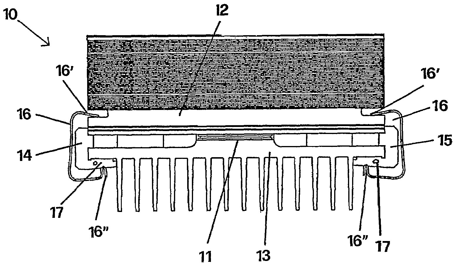
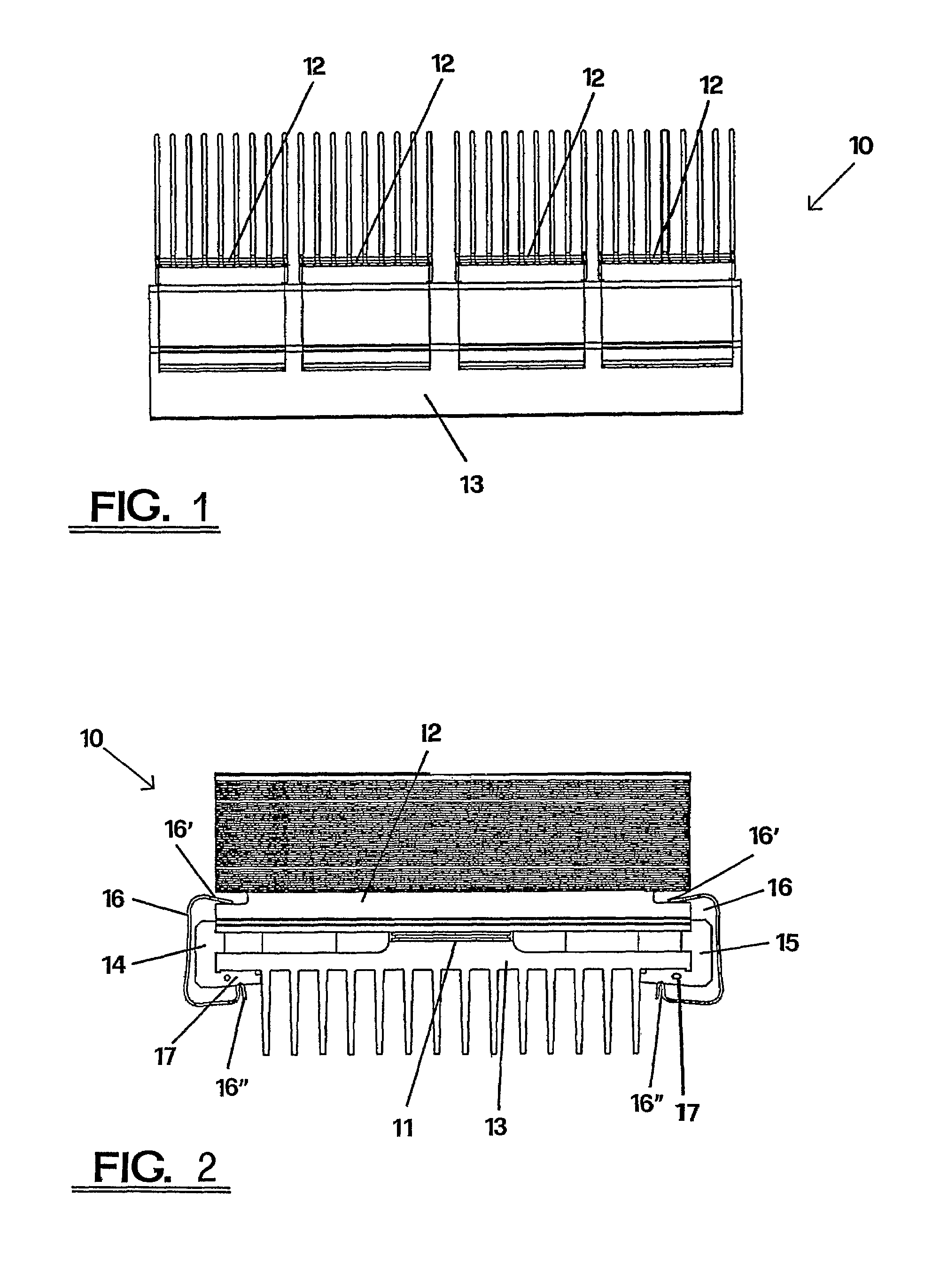
[0008]Referring to the FIGS. of the drawing, numeral 10 generally designates a heat pump comprising at least a thermoelectric module 11 connected to a first heat exchanger 12, which thermally contacts the a hot side of the thermoelectric module, and to a second heat exchanger 13, which thermally contacts a cold side of the thermoelectric module.

[0009]The configuration of the thermoelectric heat pump 10 provides an array of thermoelectric modules 11 thermally connected one another in parallel, wherein a hot side of each thermoelectric module 11 thermally contacts a separate heat exchanger, whereas a cold side thermally contacts a heat exchanger which is common to all the thermoelectric modules 11 of the array.

[0010]The configuration of the thermoelectric heat pump 10 may also provide an array of thermoelectric modules 11 thermally connected one another in parallel, wherein each hot side and cold side of the thermoelectric modules 11 contact separate heat exchangers, or alternatively ...


PUM


Abstract

The thermoelectric heat pump comprises one or more thermoelectric modules having a hot side connected to a first heat exchanger and a cold side connected to a second heat exchanger, and is characterized in that it comprises a pair of elongated bar-like elements made of an electrically and thermally insulating material which are arranged at two parallel sides of the heat exchangers, at least partly interposed between facing flanges of said heat exchangers, at least one of said elongated bar-like elements including electric conductors for supplying power to the thermoelectric modules, as well as conductors for supplying control signals therefor, and that said heat exchangers contacting the thermoelectric modules are linked one another via a plurality of fasteners, each fastener being formed of a substantially C-shaped metal clip.

Description

TECHNICAL FIELD[0001]The present invention generally relates to the filed of thermoelectricity, and particularly an improved kind of thermoelectric heat pump.PRIOR ART[0002]Thermoelectric heat pumps are solid state devices which make use of a thermoelectric effect known as Peltier effect for refrigerating and / or heating purposes in the domestic and / or industrial field.[0003]These devices generally include a thermoelectric module which is formed of an array of thermoelectric elements consisting in conductors or semiconductors of the P and N type which are connected electrically in series and thermally in parallel together. The thermoelectric elements are assembled on supports of electrically insulating and thermally conducting material which is generally a ceramic-like material. The thermoelectric modules are connected to heat exchangers for forming a heat pump intended for domestic and industrial applications.[0004]The thermoelectric heat pumps known in the art generally exhibit som...

Claims


Application Information

Patent Timeline
Patent Type & Authority Patents(United States)
IPC IPC(8): F25B21/02H01L35/10H01L35/32
CPCH01L35/10H01L35/32F25B21/02F25B2321/023H01L2924/0002H01L2924/00H10N10/82H10N10/17
Inventor CODECASA, MATTEOPASTORINO, GIORGIO
Owner PELTECH
Why Eureka
Try Eureka