Methods and apparatus for measuring impact toughness of a tie rod end

Inactive Publication Date: 2008-04-22
HONDA MOTOR CO LTD
View PDF11 Cites 23 Cited by
  • Summary
  • Abstract
  • Description
  • Claims
  • Application Information

AI Technical Summary

Benefits of technology

[0005]In accordance with another embodiment of the present invention, a method is provided for measuring impact toughness of a tie rod end. The method comprises providing a pendulum-type impact testing machine having a base, a hammer, and a measurement apparatus. The hammer is configured for pivotable movement with respect to the base, about a pivot axis, and over an arc defining a first plane. The measurement apparatus is configured to measure force arising from impact of the hammer upon an object secured with respect to the base. A tie rod end is provided which has a first member and a second member. The first member comprises a threaded end and at least a portion of a pivot ball joint opposite the threaded end. A proximal end of the second member interfaces said pivot ball joint such that a distal end of the second member is pivotable between limit positions with respect to the threaded end of the first member. A support apparatus is attached to the base of the pendulum-type impact testing machine. The threaded end of the tie rod end is attached to the support apparatus such that the distal end reaches one of the limit positions in which a longitudinal axis of the second member lies within a second plane perpendicular with the first plane and parallel with or inc

Problems solved by technology

In many applications, such as when used in vehicular steering systems, tie rod ends are subjected to significant impact loading.
If a tie rod end of inadequate toughness is selected, the tie rod end can be prone to premature failure, thereby resulting in catastrophic failure of the associated equipment.
However, conventional methods and apparatuses do not allow for adequate testing of tie rod ends to ensure their ability to exhibit a predetermined amount of impact toughness.

Method used


Image

  • Methods and apparatus for measuring impact toughness of a tie rod end
  • Methods and apparatus for measuring impact toughness of a tie rod end
  • Methods and apparatus for measuring impact toughness of a tie rod end

Examples


Embodiment Construction

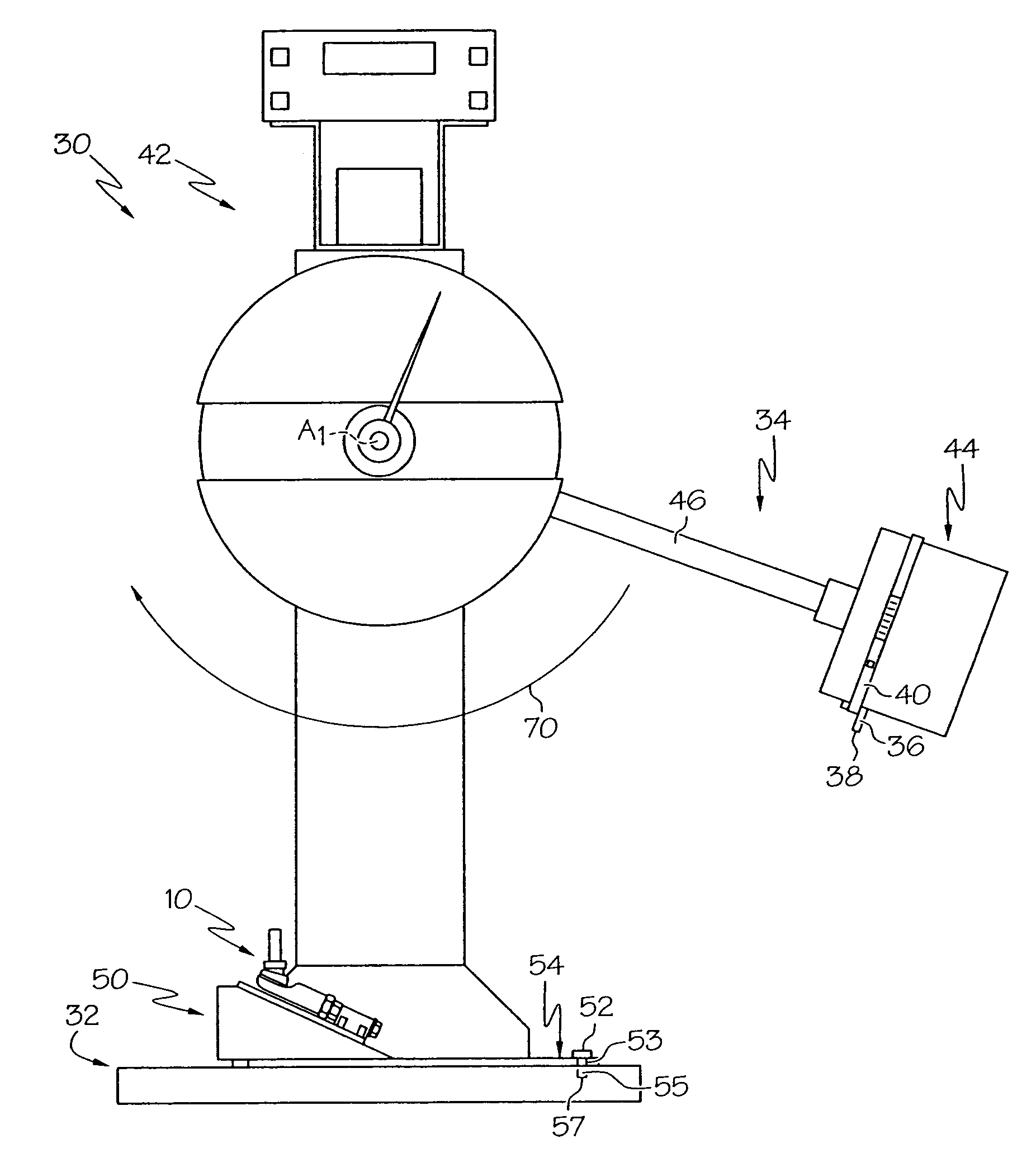
[0015]Embodiments of the present invention and its operation are hereinafter described in detail in connection with the views and examples of FIGS. 1-7, wherein like numbers indicate the same or corresponding elements throughout the views. A pendulum-type impact testing machine 30 is shown in FIG. 4 to include a base 32, a hammer 34, and a measurement apparatus 42. The hammer 34 comprises an arm 46 and a head 44. In use, an object for testing is secured with respect to the base 32, and the hammer 34 is then pivoted about a pivot axis A1 with respect to the base 32, over an arc 70, and until the head 44 impacts the object. The arc 70 traveled by the hammer 34 defines a first plane P1. The pendulum-type impact testing machine 30 can be configured such that the rotational speed and / or force of the hammer 34 along arc 70 can be adjusted as desired for testing of a particular object. The measurement apparatus 42 is configured to measure force arising from impact of the hammer 34 upon the...


PUM


Abstract

A method is provided for measuring impact toughness of a tie rod end through use of a pendulum-type impact testing machine. The method includes attaching a first member of the tie rod end with respect to a base of the pendulum-type impact testing machine. The pendulum-type impact testing machine is operated such that the hammer impacts the second member of the tie rod end. Force arising from the impact of the hammer upon the second member of the tie rod end is measured. A support apparatus is also provided for supporting the tie rod end in a position to receive contact from the hammer of the pendulum-type impact testing machine.

Description

TECHNICAL FIELD[0001]The present invention relates to methods and apparatus for measuring the impact toughness of a tie rod end through use of a pendulum-type impact testing machine.BACKGROUND OF THE INVENTION[0002]Tie rod ends are often employed as components of vehicles and other equipment. In one particular application, a tie rod end is employed as part of a vehicle's suspension system to facilitate attachment of a vehicle's tie rod to a wheel spindle or king pin of the vehicle. An example of a conventional tie rod end 10 is depicted in FIG. 1 to include a first member 12 and a second member 14. The first member 12 has a threaded end 16 and an opposite end 18 disposed along a first longitudinal axis L1. The opposite end 18 is shown to comprise at least a portion of a pivot ball joint 19. The second member 14 has a proximal end 20 and a distal end 22 disposed along a second longitudinal axis L2. The proximal end 20 of the second member 14 interfaces the pivot ball joint 19, wherei...

Claims


Application Information

Patent Timeline
IPC IPC(8): G01M7/00
CPCG01M7/08
Inventor ABKE, TIMOTHY A.
Owner HONDA MOTOR CO LTD
Why Eureka
Try Eureka