Controller-integrated rotating electrical machine

Inactive Publication Date: 2017-11-30
DENSO CORP
View PDF0 Cites 2 Cited by
  • Summary
  • Abstract
  • Description
  • Claims
  • Application Information

AI Technical Summary

Benefits of technology

[0039]The use of the cable retainer attached to the magnetic member facilitates securement of the cable to the controller-integrated rotating electrical machine without use of additional f

Problems solved by technology

The electrical drive mechanism, however, faces a drawback in that the sensing device of the rotational angle sensor is arranged closer to the object which is attached to the shaft of the motor and directly detected by the sensing device, so that they are adversely affected by magnetic flux generated by the rotating electrical machine, thereby resulting in a reduced measurement accuracy of the rotational angle sensor.
The electrical drive mechanism has the sensing device secured to the control board through the connector and also has power modules mounted on the control board, thereby result

Method used


Image

  • Controller-integrated rotating electrical machine
  • Controller-integrated rotating electrical machine
  • Controller-integrated rotating electrical machine

Examples


first embodiment

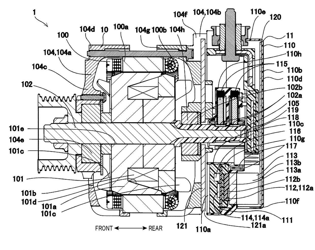
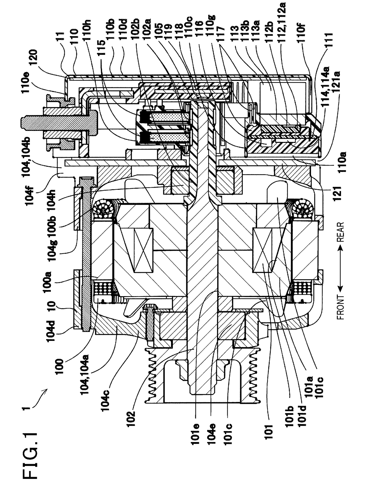
[0054]The controller-integrated rotating electrical machine 1 shown in FIG. 1 is a device which is supplied with electric power from a storage battery mounted in the vehicle to produce a drive force to move the vehicle and to which a drive force or torque is supplied from an engine, such as an internal combustion engine mounted in the vehicle, to charge the storage battery. The controller-integrated rotating electrical machine 1 is equipped with the rotating electrical machine 10 and the control device 11.

[0055]In the following discussion, an axial direction represents a direction in which an axis of rotation of the rotor 101 of the rotating electrical machine 10 extends or a direction parallel to the axis of rotation of the rotor 10. As indicated in FIG. 1, a front or a front side represents a direction from the control device 11 to the rotating electrical machine 10 in the axial direction. A rear or a rear side represents a direction from the rotating electrical machine 10 to the ...

second embodiment

[0128]FIG. 4 illustrates the controller-integrated rotating electrical machine 1 according to the second embodiment which has the magnetic member 120 secured to the second wiring board 118. Other arrangements are identical with those in the first embodiment.

[0129]The magnetic member 120, as clearly illustrated in FIG. 4, has a major surface adhered or closely attached to a rear major surface of the resin 110g which hermetically seals the second wiring board 118. In other words, the magnetic member 120 is secured to the second wiring board 118 through the resin 110g.

Beneficial Advantage

[0130]The controller-integrated rotating electrical machine 1 of this embodiment is different from that of the first embodiment only in the magnetic member 120 secured to, in other words, retained by the second wiring board 118, thus offering substantially the same advantages as those in the first embodiment.

[0131]The magnetic member 120 is, as described above, secured to the second wiring board 118, ...

second embodiments

Modifications of First and Second Embodiments

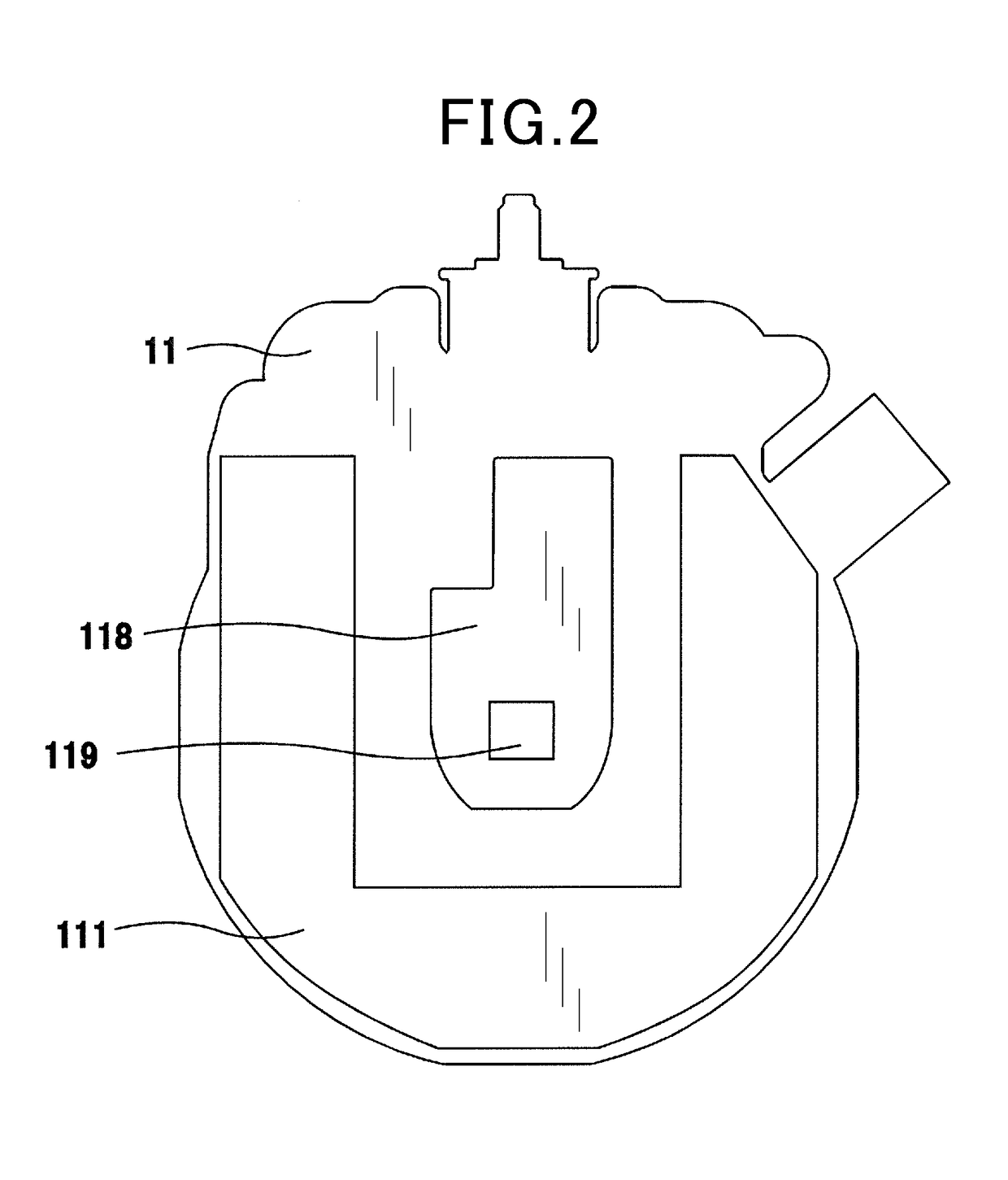
[0133]The second wiring board 118 of the first and second embodiments, as already described with reference to FIG. 2, is made of a substantially rectangular plate with the first end (i.e., the inside end) and the second end (i.e., the outside end). The second end is smaller in width than the first end. The second wiring board 118 may, however, be designed to have another configuration.

[0134]For instance, the second wiring board 118 may be formed in a wedge-shape to have a width (i.e., a dimension in the radial direction of the rotating electrical machine 10) which increases from the second end on which the angle position sensing device 119 is mounted toward the first end or alternatively formed in a gourd-shape to have a width which varies between the first and second ends.

[0135]The second wiring board 118 is, as described above, smaller in size than the first wiring board 111, but however, may be shaped to a length which extends in the r...


PUM


Abstract

A controller-integrated rotating electrical machine incudes a rotating electrical machine and a control device. The rotating electrical machine is equipped with a stator and a rotor. The control device is equipped with a control circuit for an inverter circuit and an angle position sensing device which works to measure an angular position of the rotor. The control device has first substrate on which the control circuit is mounted and a second substrate on which the angle position sensing device is mounted. The first substrate is located closer to the rotating electrical machine than the angle position sensing device is in an axial direction of the controller-integrated rotating electrical machine. This minimizes adverse effects of magnetic flux, as generated by the rotating electrical machine, on operation of the angle position sensing device, thereby enhancing a measurement accuracy of the angle positon sensing device.

Description

CROSS REFERENCE TO RELATED DOCUMENT[0001]The present application claims the benefit of priority of Japanese Patent Applications No. 2016-109476 filed on May 31, 2016 and No. 2017-19082 filed on Feb. 3, 2017, the disclosures of which are incorporated herein by reference.BACKGROUND1. Technical Field[0002]The invention relates generally to a controller-integrated rotating electrical machine equipped with a rotating electrical machine and a control device working to control operation of the rotating electrical machine.2. Background Art[0003]Controller-integrated rotating electrical machines are known which are equipped with a rotating electrical machine and a control device (also called an inverter assembly). The control device is equipped with power modules, heat sinks, connecting terminals, bus bars, and an insulator. The power modules are joined to the heat sinks through thermally conductive and electrically insulating adhesive. The connecting terminals and the bus bars are insert-mo...

Claims


Application Information

Patent Timeline
IPC IPC(8): H02P9/00H02P9/02H02P8/06H02P11/06H02P25/026
CPCH02P9/009H02P9/02H02P25/026H02P11/06H02P8/06H02K11/33H02K11/215H02K11/30H02K29/08
Inventor INAMURA, HIROSHISUZUKI, YUKIKONDO, KOJIASANO, NOBUHIROMAWATARI, YUKIYOSHIMURA, MASATAKA
Owner DENSO CORP
Why Eureka
Try Eureka