Alignment mechanism for a welding torch

a welding torch and alignment mechanism technology, applied in the field of welding devices, can solve the problems of unsatisfactory clearance, undesirable impact of the welding torch on the surrounding environmental structure, and the inability to secure the welding of various components, and achieve the effect of convenient securement and alignment of various components

Inactive Publication Date: 2006-10-12
ILLINOIS TOOL WORKS INC
View PDF3 Cites 21 Cited by
  • Summary
  • Abstract
  • Description
  • Claims
  • Application Information

AI Technical Summary

Benefits of technology

[0007] In accordance with one exemplary embodiment, the present invention provides a welding torch that includes various features that facilitate securement and alignment of various components thereof. The exemplary welding torch includes a coupling member that has an interior surface that defines a central aperture that extends through this member. The coupling member also has a slot that is located in the interior surface and that is open at a first end. The exemplary torch also includes a nipple that has a sleeve and a pin member that protrudes with respect to both an inner and outer surface of the sleeve. Furthermore, the exemplary torch has a neck assembly that includes a second slot.

Problems solved by technology

Because the movements of the welding torch are often automated, errors in alignment of its various components can lead to improper positioning of the weld on the workpiece, for instance.
In other words, the automated system, because of misalignments, may perform a welding operation on a workpiece at the wrong location.
Additionally, improper installation of the various components of the welding torch can lead to undesirable impacts of the welding torch with surrounding environmental structures.
Indeed, certain clearances may not be sufficient if the welding torch is assembled in a manner that deviates from what is expected by the automation program, for instance.
Unfortunately, various events can lead to improper positioning of the welding torch with respect to the remainder of the system.
Moreover, a technician, during installation or maintenance, may install the various components of the welding torch improperly, leading to a discrepancy between the position of the welding torch expected by the automated system and the actual position of this torch.

Method used


Image

  • Alignment mechanism for a welding torch
  • Alignment mechanism for a welding torch
  • Alignment mechanism for a welding torch

Examples


Embodiment Construction

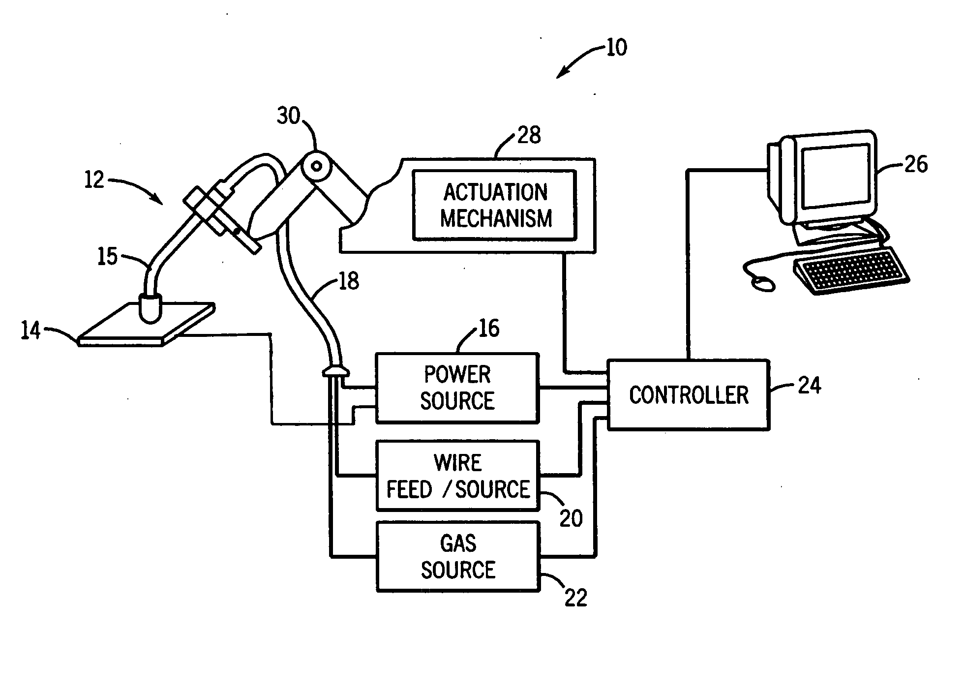
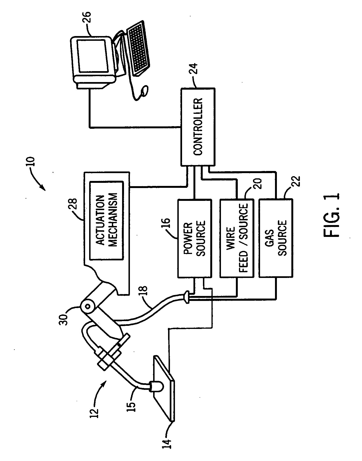
[0014] Turning to the figures, FIG. 1 illustrates an exemplary gas shielded and wire-feed robotic welding system 10. Prior to continuing, however, it is worth noting that the following discussion merely relates to exemplary embodiments of the present invention. As such, the appended claims should not be viewed a limited to those embodiments discussed herein. Indeed, the present invention provides benefits to both robotic and non-robotic welding systems as well as to both shielded and non-shielded welding devices. In summary, the present invention, which, in a general sense, relates to improved apparatus and methods for component alignment, is applicable to a vast number of systems and devices in which alignment of a resource providing component is a concern and should not be limited to welding systems. Indeed, the present invention provides benefits to fluid spray systems, for example.

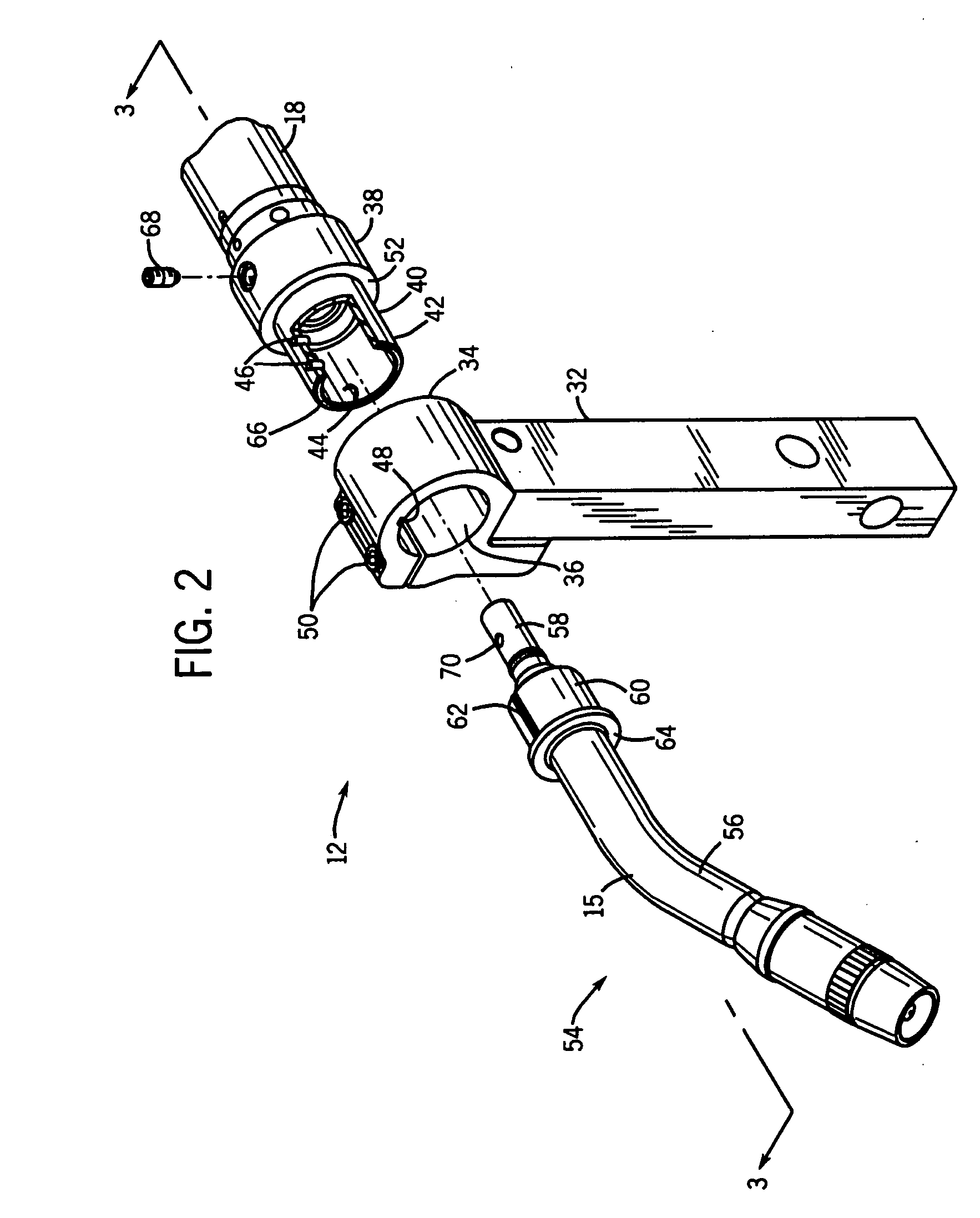
[0015] Returning to the exemplary welding system 10, it includes a welding torch 12 that defines t...


PUM

PropertyMeasurementUnit
frictionaaaaaaaaaa
electrical currentaaaaaaaaaa
electricallyaaaaaaaaaa

Abstract

In accordance with one exemplary embodiment, the present invention provides a welding torch that includes features facilitating aligned assembly of various components of the welding torch with respect to one another. For example, the welding torch includes a nipple that carries a pin member extending from both an inner peripheral surface and an outer peripheral of a sleeve of the nipple. This pin engages with a slot on a coupling member and a slot on a neck assembly, thereby facilitating proper alignment of the neck assembly, coupling member, and nipple with respect to one another. Moreover, the engagement between the pin member and the slots block pivotal displacement of neck assembly, coupling member, and neck assembly with respect to one another. Advantageously, the use of a single pin member for both slots presents a more judicious construction, leading to reduced manufacturing costs, for instance.

Description

BACKGROUND [0001] The present invention relates generally to welding devices and, more particularly, to methods and apparatus for securing and aligning various components of a welding torch with respect to one another. [0002] A common metal welding technique employs the heat generated by electrical arcing to transition workpieces to a molten state, for welding the workpieces together. One technique that employs this arcing principle is wire-feed welding. At its essence, wire-feed welding involves routing current from a power source and into a wire electrode that is brought into close proximity with the workpieces. When close enough, current arcs from the wire electrode to the workpiece, completing a circuit and generating sufficient heat to weld the workpieces to one another. Often, the wire electrode is consumed and becomes part of the weld itself. This technique is commonly referred to in the industry as gas metal arc welding (GMAW or MIG). [0003] In many industrial settings, such...

Claims


Application Information

Patent Timeline
Patent Type & Authority Applications(United States)
IPC IPC(8): B23K9/173
CPCB23K9/323
Inventor GIESE, WILLIAM R.WARNING, ROBERTJANSMA, JEREMY
Owner ILLINOIS TOOL WORKS INC
Why Eureka
Try Eureka