Device for determining at least one parameter of a medium flowing in a conduit and having a separation opening in the bypass passage

a technology of at least one parameter and a bypass passage, which is applied in the direction of measurement devices, volume/mass flow measurement, instruments, etc., can solve the problem of more difficult to achieve complete prevention of flow detachment, and achieve the effect of reducing size, low flow acceleration, and aerodynamically favorable contour

Active Publication Date: 2008-04-22
ROBERT BOSCH GMBH
View PDF7 Cites 28 Cited by
  • Summary
  • Abstract
  • Description
  • Claims
  • Application Information

AI Technical Summary

Benefits of technology

[0004]The device of the present invention for determining at least one parameter of a medium flowing in a conduit has the advantage over the related art that the regions of detached flow at the side walls of the bypass section are considerably reduced in size because the flow returns sooner into contact with the side wall provided with the separation opening, as viewed in the main flow direction, thereby reducing pressure losses in the area of the side wall provided with the separation opening and preventing unwanted flow pulsations. The flow guide wall located behind the separation opening, as viewed in the main flow direction, requires only little additional manufacturing effort and can, for example, be economically injection-molded with the conduit member to form a single piece.
[0008]It is also advantageous to combine the flow guide wall with a flow deflector element located before the bypass section, as viewed in the main flow direction; the flow deflector element having at least one deflection surface which faces the main flow direction and which, starting at an apex line spaced apart from the bypass section, is uniformly curved on both sides toward the two side walls in such a manner that the ends of the deflection surface which face away from the apex line are flush with the side walls. Additionally, a turbulence-generating structure may be provided on, or at least in the immediate proximity of, the deflection surface of the bypass section, at least before the side wall provided with the separation opening, as viewed in the main flow direction; this structure generating turbulences in the boundary layer of the flow at this side wall of the bypass section. The combination of the flow guide wall behind the bypass section with the flow deflector element before the bypass section largely prevents flow detachment on the side wall provided with the separation opening of the bypass section.
[0009]In the case of large inside diameters of the conduit member, disadvantageous flow detachments can occur on the outer surfaces of the flow guide wall due to the low flow velocities (very small Reynolds numbers in relation to the length dimension of the flow guide wall in the main flow direction) and because of the low flow acceleration at the location of the sensor device; the flow detachments in turn being capable of causing pulsations. To avoid this, it is advantageous for the flow guide wall to be provided, at least on one outer surface, with turbulence-generating structures formed, for example, by a row of projections which are preferably arranged periodically along a line and protrude from the outer surface of the flow guide wall, and which are preferably located in the portion of the flow guide wall facing the main flow direction and, in particular, form a comb-like, battlement-like, or jagged pattern. The projections make the flow boundary layer turbulent, causing increased momentum exchange between slower and faster portions of the flow. The turbulences generated counteract a detachment from the flow guide wall, thereby making it possible to prevent unwanted detachment regions at the flow guide wall.

Problems solved by technology

This is based on the idea that complete prevention of flow detachment is more difficult to achieve than localizing the flow detachment to one side of the bypass section which is not the side provided with the separation opening.

Method used


Image

  • Device for determining at least one parameter of a medium flowing in a conduit and having a separation opening in the bypass passage
  • Device for determining at least one parameter of a medium flowing in a conduit and having a separation opening in the bypass passage
  • Device for determining at least one parameter of a medium flowing in a conduit and having a separation opening in the bypass passage

Examples


Embodiment Construction

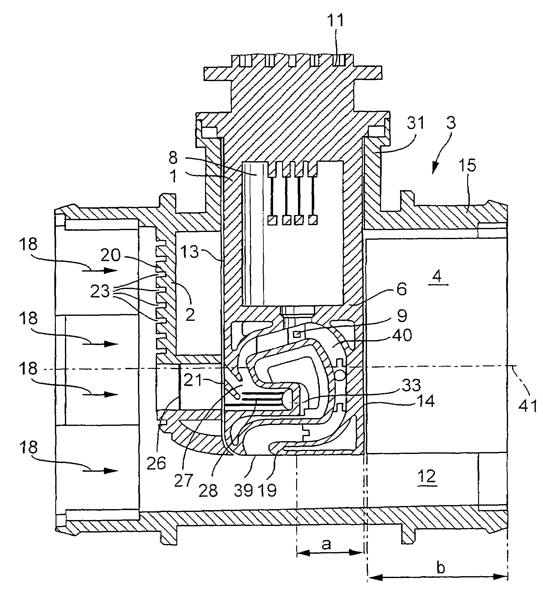
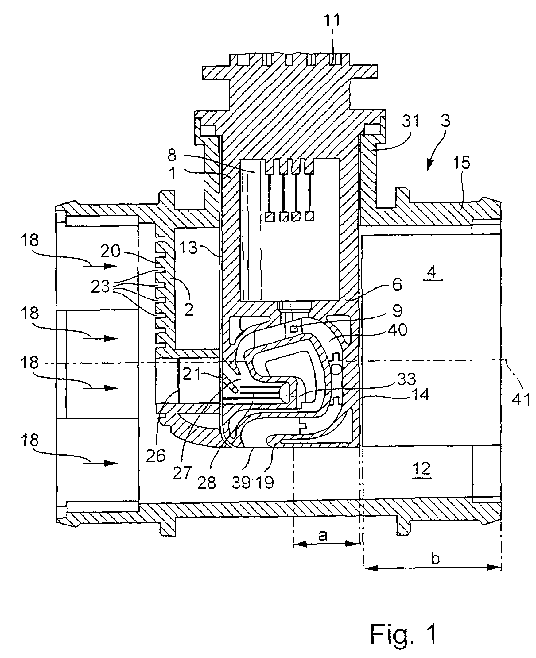
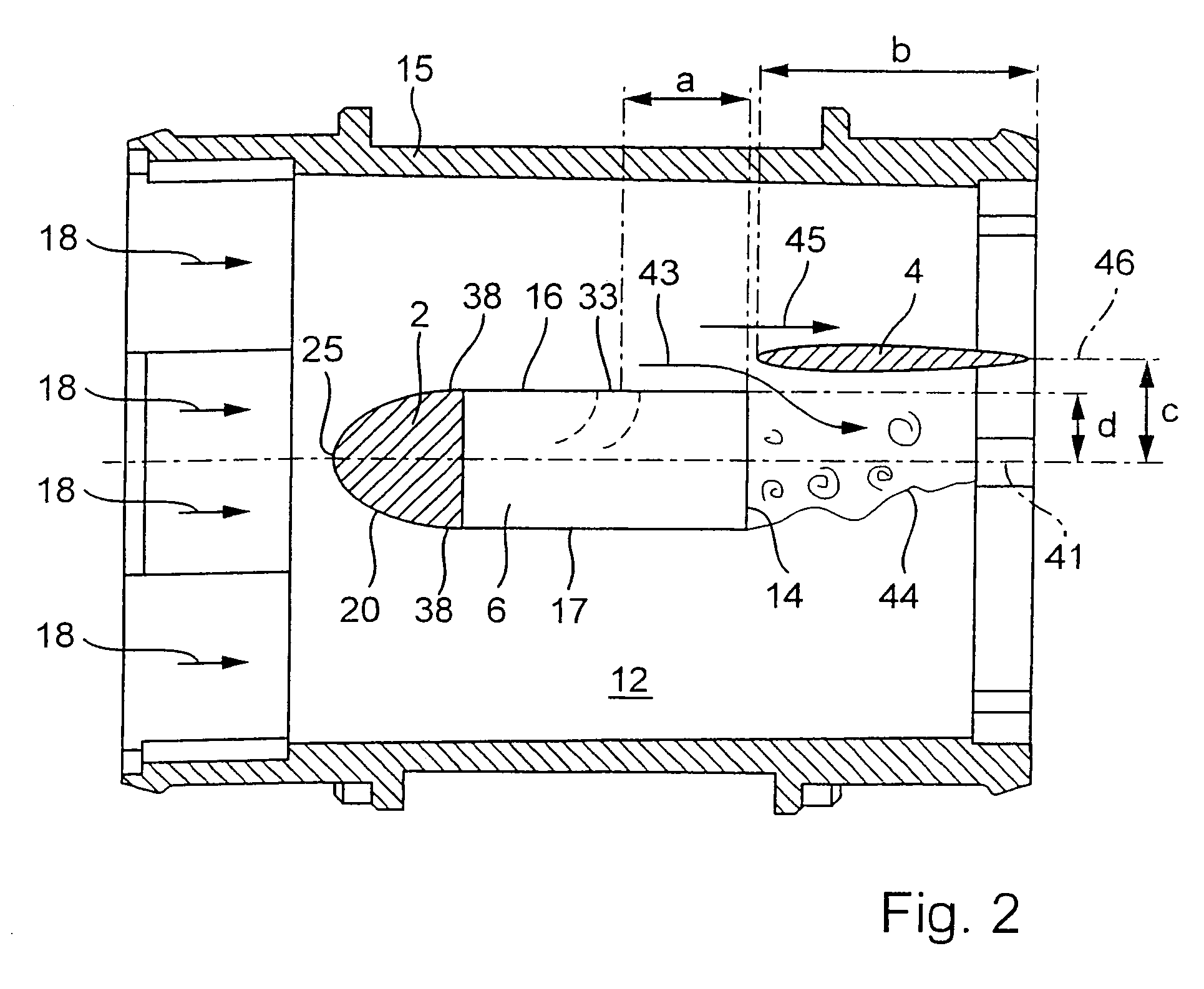
[0015]FIG. 1 shows a conduit member 3 having an approximately cylinder jacket-shaped wall 15 which surrounds a conduit passage 12 in which a medium flows in a main flow direction. In FIG. 1, the main flow direction is from left to right and is marked by corresponding arrows 18. The main flow direction is defined as the direction in which the medium mainly flows through the conduit passage, from the inlet to the outlet of conduit member 3, even if locally forming vortices and local regions of detached flow have differences in the flow from the main flow direction or if temporary changes in direction occur. Here, the main flow direction runs parallel to center axis 41 of cylinder jacket-shaped wall 15 of conduit member 3. Conduit member 3 can be inserted, for example, into an intake pipe of an internal combustion engine. The medium is, for example, the air flowing to the internal combustion engine.

[0016]A sensor device 1 is mounted on conduit member 3 in such a manner that a bypass se...


PUM


Abstract

Devices for determining at least one parameter of a medium flowing in a conduit, in particular for determining the air-mass flow in the intake tract of an internal combustion engine, including a conduit member and sensor device having a bypass section are already known. To prevent flow detachment at the side walls of the bypass section, it is proposed that a flow guide wall running substantially parallel to the side wall provided with the separation opening of the bypass section be arranged in the conduit member behind the separation opening, as viewed in the main flow direction; the length dimension b of the flow guide wall, as viewed in the main flow direction, being equal to or greater than the distance a of the separation opening from the rear wall; and the distance c of the flow guide wall from the center axis of the conduit member being greater than or equal to the distance d of the side wall provided with the separation opening of the bypass section from the center axis.

Description

FIELD OF THE INVENTION [0001]The present invention relates to a device for determining at least one parameter of a medium flowing in a conduit.BACKGROUND INFORMATION [0002]A device of this type is known, for example, from German Published Patent Application No. 101 35 142 and is used, for example, in the intake tract of an internal combustion engine to determine the air-mass flow passed through a conduit to the internal combustion engine. A portion of a sensor device provided with a bypass section is inserted into the conduit member through an insertion opening. The bypass section features a channel structure having an inlet region from which a measuring channel provided with a measuring element branches off. The inlet region further has a separation zone having at least one separation opening which opens into the conduit passage at at least one side wall of the bypass section. The separation zone is used to remove liquid and / or solid particles from the channel structure, thereby pr...

Claims


Application Information

Patent Timeline
Patent Type & Authority Patents(United States)
IPC IPC(8): G01F1/68G01F1/684G01F5/00
CPCG01F1/6842G01F5/00
Inventor KONZELMANN, UWEMARBERG, HENNINGGMELIN, CHRISTOPH
Owner ROBERT BOSCH GMBH
Why Eureka
Try Eureka